Wednesday, 8 October 2014

PLC Programming Introduction | Sofcon


One method of the PLC programming is using ladder diagram method. Ladder diagram consists of a descending line on the left, with lines branching to the right. This line is the line branching instructions. Throughout this instruction line consists a combination of logic that states when and how the existing instructions on the right side are done.

Ladder Diagram Example


The logic combination of ladder diagram as following:

A. Instruction LOAD (LD) and LOAD NOT (LD NOT)

The first condition that starts any logic block in the ladder diagram associated with LOAD instruction (LD) or LOAD NOT (LD NOT). Each of these instructions requires one line of mnemonic code.


B. Instruction AND and AND NOT

If two or more conditions that are connected in series on the same instruction line, then the first condition using LD or LD instruction and the remainder NOT use the instructions AND or AND NOT.

AND instruction can be imagined to produce ON if both conditions are linked with this instruction in all ON conditions, if any one in the OFF state, let alone both OFF, the instruction will always result AND OFF too.

C. Instruction OR and OR NOT

If two or more conditions connected in parallel, meaning in a different line of instructions and then joined again in the same instruction line, then the first condition associated with LD or LD instruction and the rest is NOT related to the instructions OR or OR NOT.

In this case imaginable OR instruction will always result in ON execution condition when any one of two or more conditions connected with this instruction in the ON condition.

Sofcon Arrange Workshope in RCEW ( Rajasthan College of Engineers for Women) Bhakrota, Jaipur....

The workshop was highly appreciated by 90 students of Electrical Branch ( II, III & Final Year Students). Feedback was positive.


Engineers detailed.
1. Mr. KL Swami ( Training Head)
2. Mr. Prem Kishan Rana (Automation Engineer)
3. Mr. Prithavraj (Embedded Engineer) Under Training


Tuesday, 7 October 2014

PLC Real Time Clock Using Arduino programming at Sofcon


PLC real time clock using arduino and real time clock module. for real time module use DS3231 RTC Board. The way it works is: Arduino reads data from the DS3231, this data is sent directly to the PLC memory. and for setting the date and time via the DS3124 and computer by using visual basic net (VB.Net)

PLC real time clock process:
1. Read date and time from DS3231 RTC Board with Arduino via I2C communication
2. Send data to PLC with Arduino via RS232 communication and PLC Protocol
3. Receive data in PLC data memory
Flow process of the PLC Real TIme Clock:

 Arduino Source Code 

#include <Wire.h>;
const int DS1307 = 0x68;
byte second = 0;
byte minute = 0;
byte hourofday = 0;
byte dayofweek = 0;
byte date = 0;
byte month = 0;
byte year = 0;
byte set[7];
const char delimiter = ',';
String  message;
byte i;
int y;

void setup() {
  Wire.begin();
  Serial.begin(9600,SERIAL_8E1);//9600,8,Even,1
  Serial.setTimeout(800);
}

void loop() {
  sendTime();  
  message = Serial.readString();  //= "year,month,date,week,hour,minute,second";
  incomeTime(); 
}
byte decToBcd(byte val) {
  return ((val/10*16) + (val%10));
}
byte bcdToDec(byte val) {
  return ((val/16*10) + (val%16));
}

void incomeTime() { 
  i=0;
  y=-1;  
  do
  {
      y = message.indexOf(delimiter);
      if(y != -1)
      {
          if(i<=5)set[i]=message.substring(0,y).toInt();
          message = message.substring(y+1, message.length());
          i++;
      }
      else
      {
         if(message.length() > 0 && i==6)
           set[i]=message.toInt();         
      }
   }
   while(y >=0);
   
   if (i==6){
     if(set[0]>=0 && set[0]<=99){
       if(set[1]>=1 && set[1]<=12){
         if(set[2]>=1 && set[2]<=31){
           if(set[3]>=1 && set[3]<=7){
             if(set[4]>=0 && set[4]<=23){
               if(set[5]>=0 && set[5]<=59){
                 if(set[6]>=0 && set[6]<=59){
                   setTime();
                 }
               }
             }
           }
         }
       }
     }
   }

}
void setTime() { 
  year =set[0]; 
  month =set[1]; 
  date =set[2]; 
  dayofweek =set[3]; 
  hourofday =set[4]; 
  minute =set[5]; 
  second = set[6];
  Wire.beginTransmission(DS1307);
  Wire.write(byte(0));
  Wire.write(decToBcd(second));
  Wire.write(decToBcd(minute));
  Wire.write(decToBcd(hourofday));
  Wire.write(decToBcd(dayofweek));
  Wire.write(decToBcd(date));
  Wire.write(decToBcd(month));
  Wire.write(decToBcd(year));
  Wire.write(byte(0));
  Wire.endTransmission();
}

void sendTime() {
  readTime();
  int VB0 = second;// VB0=SECOND : 0 to 59
  int VB1 = minute;//VB1=MINUTE : 0 to 59
  int VB2 = hourofday;//VB2=HOUR OF DAY : 0 to 23
  int VB3 = date;//VB3= DATE : 1 to 31
  int VB4 = month;//VB4= MONTH : 1 to 12
  int VB5 = dayofweek;//VB5= DAY OF WEEK : 1=SUNDAY, 2=MONDAY, 3=TUESDAY, 4=WEDNESDAY, 5=THURSDAY, 6=FRIDAY, 7=SATURDAY
  int VB6 = year;//VW6= YEAR 00 to 99

  int VWstart = 0; //Start from VW0
  int VWcount = 4; 

  byte str_write[45];
  long Temp_FCS=0;
  int i;
                    
  str_write[1] = (byte)((VWcount * 2) + 31);
  str_write[2] = (byte)str_write[1];
  str_write[24] = (byte)(VWcount * 2);
  str_write[16] = (byte)(str_write[24] + 4);
  str_write[33] = (byte)((VWcount * 16) / 256);
  str_write[34] = (byte)((VWcount * 16) % 256);

  str_write[29] = (byte)((VWstart * 8) / 256);
  str_write[30] = (byte)((VWstart * 8) % 256);

  str_write[0] = (byte)0x68;//H68
  str_write[3] = (byte)0x68;//H68
  str_write[4] = (byte)0x02;//H2
  str_write[5] = (byte)0x00;//H0
  str_write[6] = (byte)0x7C;//H7C
  str_write[7] = (byte)0x32;//H32
  str_write[8] = (byte)0x01;//H1
  str_write[9] = (byte)0x00;//H0
  str_write[10] = (byte)0x0;//H0
  str_write[11] = (byte)0x43;//H43
  str_write[12] = (byte)0x01;//H1
  str_write[13] = (byte)0x00;//H0
  str_write[14] = (byte)0x0E;//HE
  str_write[15] = (byte)0x00;//H0

  str_write[17] = (byte)0x05;//H5
  str_write[18] = (byte)0x01;//H1
  str_write[19] = (byte)0x12;//H12
  str_write[20] = (byte)0x0A;//HA
  str_write[21] = (byte)0x10;//H10
  str_write[22] = (byte)0x02;//H2
  str_write[23] = (byte)0x00;//H0

  str_write[25] = (byte)0x00;//H0
  str_write[26] = (byte)0x01;//H1  
  str_write[27] = (byte)0x84;//H84  
  str_write[28] = (byte)0x00;//H0

  str_write[31] = (byte)0x00;//H0
  str_write[32] = (byte)0x04;//H4


  str_write[35] = (byte)VB0;
  str_write[36] = (byte)VB1;

  str_write[37] = (byte)VB2;
  str_write[38] = (byte)VB3;

  str_write[39] = (byte)VB4;
  str_write[40] = (byte)VB5;

  str_write[41] = (byte)VB6;
  str_write[42] = (byte)0;

  for (i = 4; i <= 42; i++)
  {
      Temp_FCS = Temp_FCS + str_write[i];
  }
  str_write[43] = (byte)(Temp_FCS % 256);
  str_write[44] = (byte)0x16;//H16

  Serial.write(str_write, sizeof(str_write));

  delay(100);
    byte str_val[6];
    str_val[0] = (byte)0x10;//H10; 
    str_val[1] = (byte)0x02;//H2;
    str_val[2] = (byte)0x00;//H0;
    str_val[3] = (byte)0x5C;//H5C;
    str_val[4] = (byte)0x5E;//H5E;
    str_val[5] = (byte)0x16;//H16;
    Serial.write(str_val, sizeof(str_val));
  delay(100);
}


void readTime() {
  Wire.beginTransmission(DS1307);
  Wire.write(byte(0));
  Wire.endTransmission();
  Wire.requestFrom(DS1307, 7);
  second = bcdToDec(Wire.read());
  minute = bcdToDec(Wire.read());
  hourofday = bcdToDec(Wire.read());
  dayofweek = bcdToDec(Wire.read());
  date = bcdToDec(Wire.read());
  month = bcdToDec(Wire.read());
  year = bcdToDec(Wire.read());
}

}

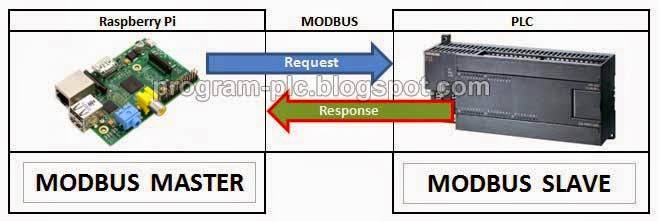
Modbus RTU Communication Between PLC and Raspberry Pi Using Python

Modbus communication in these applications using serial communication / RS232 and Modbus RTU.
This application use simple modbus with Python programming on Raspberry Pi, and not use modbus from a third party.

Modbus RTU Communication Between PLC and Raspberry Pi

For the hardware used in this application:
1. PLC
2. Raspberry Pi (Only for setting, using: monitor, keyboard, mouse, adapter, flash disk)
3. Serial PLC Cable
4.Serial Module ,and
5. Serial Crossover Connector.
For the connection beetween PLC and Raspberry Pi, Raspberry Pi Setting (Auto Login, Install PySerial, Setup UART Pins, Auto Run Python after Booting) :


Connection of Modbus RTU Communication Between PLC and Raspberry Pi:

Connection of PLC and Raspberry Pi

About Modbus:
Modbus application using function code 03, and function code 16. for this function code, you can go to the link:
http://program-plc.blogspot.com/2014/09/how-to-make-simple-modbus-rtu.html


Python Code of Modbus Communication on Raspberry Pi:

import serial
import random
#Sub Program
#CRC Calculation
def CRCcal(msg):
    #CRC (Cyclical Redundancy Check) Calculation
    CRC = 0xFFFF
    CRCHi = 0xFF
    CRCLo = 0xFF
    CRCLSB = 0x00
    for i in range(0, len(msg)-2,+1):
        CRC = (CRC ^ msg[i])
        for j in range(0, 8):
            CRCLSB = (CRC & 0x0001);
            CRC = ((CRC >> 1) & 0x7FFF)
            if (CRCLSB == 1):
                CRC = (CRC ^ 0xA001)
    CRCHi = ((CRC >> 8) & 0xFF)
    CRCLo = (CRC & 0xFF)
    return (CRCLo,CRCHi) 
#CRC Valdation
def CRCvalid(resp):
    CRC = CRCcal(resp)
    if (CRC[0]==resp[len(resp)-2]) & (CRC[1]==resp[len(resp)-1]):return True
    return False
#Modbus Function Code 16 = Preset Multiple Registers   
def Func16Modbus(slave,start,values):
    Slave_Address = slave
    Function = 16
    Starting_Address = start
    NumberofRegisters = len(values)
    Byte_Count = NumberofRegisters * 2
    message = [0 for i in range(9 + 2 * NumberofRegisters)]  
    #index0 = Slave Address
    message[0] = (Slave_Address & 0xFF)
    #index1 = Function
    message[1] = (Function & 0xFF)
    #index2 = Starting Address Hi
    message[2] = ((Starting_Address >> 8) & 0xFF)
    #index3 = Starting Address Lo
    message[3] = (Starting_Address & 0xFF)
    #index4 = Number of Registers Hi
    message[4] = ((NumberofRegisters >> 8) & 0xFF)
    #index5 = Number of Registers Lo
    message[5] = (NumberofRegisters & 0xFF)
    #index6 = Byte Count
    message[6] = (Byte_Count & 0xFF)
    for i in range(0, NumberofRegisters):
        #Data Hi, index7 and index9
        message[7 + 2 * i] = ((values[i] >> 8) & 0xFF)
        #Data Lo, index8 and index10
        message[8 + 2 * i] = values[i] & 0xFF
    #CRC (Cyclical Redundancy Check) Calculation
    CRC = CRCcal(message)
   
    #index11= CRC Lo
    message[len(message) - 2] = CRC[0]#CRCLo
    #index12 = CRC Hi
    message[len(message) - 1] = CRC[1]#CRCHi
    if ser.isOpen:       
        ser.write("".join(chr(h) for h in message))
        reading = ser.read(8)
        response = [0 for i in range(len(reading))]
        for i in range(0, len(reading)):
            response[i] = ord(reading[i])
        if len(response)==8:
            CRCok = CRCvalid(response)
            if CRCok & (response[0]==slave) & (response[1]==Function):return True
    return False
#Modbus Function Code 03 = Read Holding Registers
def Func03Modbus(slave,start,NumOfPoints):
    #Function 3 request is always 8 bytes
    message = [0 for i in range(8)] 
    Slave_Address = slave
    Function = 3
    Starting_Address = start
    Number_of_Points = NumOfPoints
    #index0 = Slave Address
    message[0] = Slave_Address
    #index1 = Function
    message[1] = Function
    #index2 = Starting Address Hi
    message[2] = ((Starting_Address >> 8)& 0xFF)
    #index3 = Starting Address Lo
    message[3] = (Starting_Address& 0xFF)
    #index4 = Number of Points Hi
    message[4] = ((Number_of_Points >> 8)& 0xFF)
    #index5 = Number of Points Lo
    message[5] = (Number_of_Points& 0xFF)
    #CRC (Cyclical Redundancy Check) Calculation
    CRC = CRCcal(message)
   
    #index6= CRC Lo
    message[len(message) - 2] = CRC[0]#CRCLo
    #index7 = CRC Hi
    message[len(message) - 1] = CRC[1]#CRCHi
   
    if ser.isOpen:       
        ser.write("".join(chr(h) for h in message))
        responseFunc3total = 5 + 2 * Number_of_Points
        reading = ser.read(responseFunc3total)
        response = [0 for i in range(len(reading))]
        for i in range(0, len(reading)):
            response[i] = ord(reading[i])
       
        if len(response)==responseFunc3total:
            CRCok = CRCvalid(response)
            if CRCok & (response[0]==slave) & (response[1]==Function):
                #Byte Count in index 3 = responseFunc3[2]
                #Number of Registers = byte count / 2 = responseFunc3[2] / 2
                registers = ((response[2] / 2)& 0xFF)
                values = [0 for i in range(registers)]
                for i in range(0, len(values)):
                    #Data Hi and Registers1 from Index3
                    values[i] = response[2 * i + 3]
                    #Move to Hi
                    values[i] <<= 8
                    #Data Lo and Registers1 from Index4
                    values[i] += response[2 * i + 4]
                   negatif = values[i]>>15
                   if negatif==1:values[i]=values[i]*-1
                return values
    return ()
#Main Program
#Serial Port 9600,8,E,1
#Serial Open
try:
        ser = serial.Serial(
                port = '/dev/ttyAMA0',
                baudrate = 9600,
                bytesize = serial.EIGHTBITS,
                parity = serial.PARITY_EVEN,
                stopbits = serial.STOPBITS_ONE,
                timeout = 0.2
        )
except Exception, e:
        raise ValueError(e)
print "START"
while 1:       
    #Serial Open Check
    if not ser.isOpen:ser.open()
    #Read of Registers
    Func03ArrayValue = Func03Modbus(1,0,2);#slave,start,number of registers
    if len(Func03ArrayValue)>0:
        for i in range(0, len(Func03ArrayValue)):
            print "Read of Registers" + str(i) + " = " + str(Func03ArrayValue[i])
    #Fill Random Value for Write
    totalvalue=2
    val = [0 for i in range(totalvalue)]
    for i in range(0, len(val)):
        val[i] = random.randrange(-32767,32767) #Random Valiue from -32767 to max 32767
    #Write of Registers
    WriteValid = Func16Modbus(1,2,val)#slave,start,array value
    if WriteValid:
        for i in range(0, len(val)):
            print "Write of Registers" + str(i) + " = " + str(val[i])


        print "#################################"


Monday, 6 October 2014

2014 Summer Training with PLC Scada HMI Sofcon


This course is perfect for students looking for a PLC or SCADA training course. At the end of this course you will have an understanding of:
  • Fundamentals of SCADA systems
  • Essentials of SCADA software configuration
  • Tricks and tips in installation of SCADA systems
  • Essentials of telecommunications links
  • Use of Industrial Ethernet in SCADA systems
  • OPC and SCADA systems
  • SCADA network security issues
  • How to troubleshoot SCADA systems
  • Specifying PLC hardware and installation criteria
  • Describe PLC software structure
  • How to write medium level PLC programs (using ladderlogic)
  • Troubleshooting a typical PLC system
  • Specifying PLC systems 

This extensive course covers the essentials of SCADA and PLC frameworks, which are regularly utilized within close relationship with one another. A choice of careful investigations are utilized to delineate the key ideas with illustrations of true meeting expectations SCADA and PLC frameworks in the water, electrical and preparing commercial enterprises.

This course will be a great chance to system with your associates, and in addition to increase noteworthy new data and strategies for your next SCADA/ PLC venture. Despite the fact that the stress of the course will be on reasonable industry points highlighting late improvements, utilizing detailed analyses, the most recent application of SCADA, PLC advances and basics will be secured.

The inexorable inquiry is which PLC is continuously utilized. We show this course concentrating on the nonexclusive PLC and utilize the open programming IEC 61131-3 standard. For particular illustrations we utilize the Allen Bradley range, yet are not offering Allen Bradley or so far as that is concerned whatever other PLC!


This course is intended to profit you with functional exceptional data on the application of PLC frameworks to the automation and methodology control commercial ventures. It is suitable for individuals who have almost no introduction to Plcs, however hope to wind up included in some or all parts of PLC installation. It means to give pragmatic counsel from masters in the field, to help you to effectively arrange, program and introduce a PLC with a shorter learning bend and more certainty. While the course is perfect for electrical technicians, experts and engineers who are new to Plcs, a great part of the material secured will be of worth to the individuals who as of now have some essential aptitudes, yet require a more extensive point of view for bigger and additionally difficult undertakings ahead. The data secured advances from the fundamentals to test even the most accomplished architect in the industry today.

PLC Scada Training | Summer Training | Sofcon


Scantime give PLC & SCADA Programming Training Courses for anybody overall who oblige industry perceived PLC & SCADA programming abilities. Understand your potential with Scantime Online and Training Center courses

We are System Integrators giving Automation Consultancy, Design and Troubleshooting administrations for the Oil & Gas, Aerospace, Automotive, Food & Drink and different commercial enterprises.

Building Services - Automation & Control Solutions

Spend significant time in PLC & HMI/ SCADA system Design and Development for Data Monitoring & Analysis, Fluid Pressure Control up to 80,000 PSI, Downtime Monitoring, Distributed Control Systems, utilizing an extensive variety of supplies, including Siemens, Allen Bradley, Mitsubishi, Omron, Schneider Plcs and Motion Control for rapid production. Programming to IEC 61131-3.

Advancement is attempted from idea and FDS to last on location Installation and Commissioning, including customer architect preparing and after deals help -

In the event that you might want to talk about any specific task with a part of our specialized staff,

if its not too much trouble

Preparing - PLC & SCADA Programming Courses

Accessible to everybody around the world. Pick up expert PLC programming building abilities from our organization who work full time in industry. Picking up expert aptitudes will help you to enhance  your vocation and future prospects.

We give industry sanction and guaranteed preparing worldwide for people and organization

engineers, and all Official Scantime Training  courses are conveyed with Industrial Certificates for Plcs programming furthermore SCADA designing outline. Programming courses are accessible Online, at our Training Center and can likewise be conveyed Onsite at your organization.

Online PLC & SCADA Training Courses:

Our preparation focus PLC & SCADA programming courses are presently accessible on the web.

Study from home or office and increase perceived proficient confirmation at your pace.

See our plan of accessible courses -

Figure out how to program Siemens, Mitsubishi, Omron, Allen Bradley and different Plcs from

essential programming for apprentices to more progressive levels of programming for the

accomplished specialist.

Preparing Center & Onsite PLC & SCADA Training:

Experience an active PLC instructional class at our preparation focus conveyed by one of our industry accomplished engineers with up to 35 Years in Industrial PLC/ SCADA methodology control.

Sofcon Workshop at Shree Cement Beawar ( RAAS) Ajmer Rajasthan


workshop ,  was conducted by Sofcon India Pvt. Ltd  at Shree Cement Beawar ( RAAS) Ajmer Rajasthan (29.09.2014 to 01 Oct 2014) for System Engineers.

Sofcon Engineers/ Trainers
1. Mr. Radhakrishanan ( Sofcon Baroda)
2. Mr. Prem Kishan Rana ( Sofcon Jaipur)