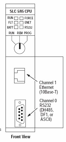
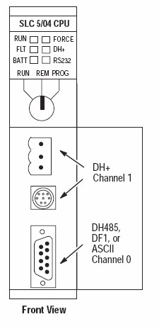
Monday 3 November 2014

Do You Know ? Next generation of Genesis HMI/SCADA Software Introduced

ICONICS, a provider of web-enabled, OPC-based, HMI/SCADA visualisation and manufacturing intelligence software for Microsoft Windows operating systems, has released v10.8 of its GENESIS64 HMI/SCADA software suite.

New enhancements include ReportWorX Express, a Cloud connector for Windows Azure, Distributed AssetWorX scalable architecture, and a new ScheduleWorX64. ICONICS has also achieved OPC Foundation certification and VMware Ready status.

ICONICS' GENESIS64 has been designed from the ground up for 64-bit operation, maximising the advantages of Intel 64-bit processors.

ICONICS President and CEO, Russ Agrusa, introduced the new 10.8 version of GENESIS64 as having “hundreds of time-saving and important new features that help transform Big Data into visual intelligence. In keeping with our technological leadership in real-time solutions for energy, industrial and building automation, GENESIS64 benefits all industries in its energy and time savings and has now also achieved the highest level of BACnet and OPC Foundation certification."

Based on its partnership with Microsoft, ICONICS has taken advantage of the Microsoft technology platform, including Microsoft .NET, SQL Server, SharePoint, Windows Server 2012 and Windows 8. Microsoft Bing, Google and Esri geospatial maps can be combined with real-time information, creating GEO SCADA solutions. Users can access information from anywhere, anytime and on any platform using the WebHMI browser-based solution and HTML5 technology.

Source:-http://www.controlengeurope.com/article/62231/Next-generation-of-Genesis-HMI-SCADA-software-introduced.aspx

Sunday 2 November 2014

SCADA Has KPI Calculation and Analysis Abilities

Siemens Industry has expanded the Simatic WinCC V7.2 SCADA software with the optional WinCC/PerformanceMonitor package for calculating and analysing plant-specific key performance indicators (KPIs). 


This expansion enables users to achieve optimisation potential for production and measures for increasing productivity, as combining results and accompanying values can reveal correlations, such as product quality in relation to suppliers.
 
Analysis with the new software package is based on the process data acquired by the SCADA systme, which is associated during runtime. The user is able to set up calculation formulas for use in WinCC, without needing any additional knowledge.
 
Several visualisations are possible for evaluation – a Gantt chart with the time sequence of states, a bar chart for analysing key performance indicators and a table for states and accompanying values. Visualisations are also available via the web in the WinCC WebNavigatorClient. 

The calculated key performance indicators can also be processed in a WinCC display, for example a line-dashboard, or in a trend display.

Career in Automation Engineering | Btech Student Must Know About Scada System

Enhanced SCADA system streamlines oil and gas operations


The new OpenEnterprise release from Emerson is said to offer ease-of-use and expanded device connectivity for communication protocols. User-friendly tools in OpenEnterprise v3 alleviate the pain of operating and managing large installations of RTUs and flow computers.


The latest OpenEnterprise v3 release introduces ‘Action Engine’ technology. An intelligent automation engine that does not require programming or scripting to manage complex sequential control which enables users to gain competitive advantage and increases operator productivity.

The Action Engine’s rapid application development and change management tools enable users to get their new system commissioned quickly and empowers them to make necessary automation changes. 

The template-based design of the software simplifies the process of building the SCADA database, enabling faster well replication and easier management of field installations with a mixture of RTU types.

“The latest OpenEnterprise v3 offers the SCADA market a step change in value when it comes to ease-of-use by offering an open SCADA platform designed to be protocol and RTU agnostic,” explained Craig Llewellyn, president, Emerson Process Management, Remote Automation Solutions. “OpenEnterprise v3 users realise increased operator productivity as new employees save on training time and are able to operate the SCADA system faster.”
OpenEnterprise v3 also offers lifecycle cost savings by an leveraging integrated wireless SCADA architecture. By integrating the WirelessHART instrumentation network along with the Distributed RTU Network, remote oil and gas operations are easier, safer, and more secure.

Unlike traditional SCADA software, OpenEnterprise v3 is not licensed by tag count and consists of scalable software tiers that are fit for applications from local metering to mega intelligent oilfield automation projects that require automation of thousands of wells. 

DCS and PLC Scada Process in Real Industries

It may surprise you to know that PLC, HMI and SCADA implementations today are consistently proving more expensive than DCS for the same process or batch application. CEE finds out more.

Traditionally, DCSs were large, expensive and very complex systems that were considered as a control solution for the continuous or batch process industries. In large systems this is, in principle, still true today, with engineers usually opting for PLCs and HMIs or SCADA for smaller applications, in order to keep costs down.

So what has changed? Integrating independent PLCs, the required operator interface and supervisory functionality, takes a lot of time and effort. The focus is on making the disparate technology work together, rather than improving operations, reducing costs, or improving the quality or profitability of a plant.

Yet a PLC/ SCADA system may have all or part of the following list of independent and manually coordinated databases.

* Each controller and its associated I/O
* Alarm management
* Batch/recipe and PLI
* Redundancy at all levels
* Historian
* Asset optimisation
* Fieldbus device management

Each of these databases must be manually synchronised for the whole system to function correctly. That is fine immediately after initial system development. However, it becomes an unnecessary complication when changes are being implemented in on-going system tuning and further changes made as a result of continuous improvement programmes.

Making changes 

Every time a change is made in one database, the others usually need to be updated to reflect that change. For example, when an I/O point and some control logic are added there may be a need to change or add a SCADA element, the historian and the alarm database. This will require the plant engineer to make these changes in each of these databases, not just one – and get it right.

In another scenario, a change may be made in an alarm setting in a control loop. In a PLC implementation there is no automatic connection between the PLC and the SCADA/ HMI. This can become a problem during start up of a new application, where alarm limits are being constantly tweaked in the controller to work out the process, while trying to keep the alarm management and HMI applications up to date with the changes and also being useful to the operator.

Today’s DCS, which are also sometimes called ‘process control systems,’ are developed to allow a plant to quickly implement the entire system by integrating all of these databases into one. This single database is designed, configured and operated from the same application.

This can bring dramatic cost reductions when using DCS technology, when compared with PLC/ SCADA (or HMI): at least in the cost of engineering. DCS hardware has always been considered as being large and expensive. This is certainly no longer the case today. DCS hardware even looks like a PLC, and the software runs on the same specification PC, with the same networking – so why the extra cost? Is it the software? Although it is true to say that DCS software can be made to be expensive – but only by buying all of the many advanced functional features that are available – and often that you would not use or need!

Where smaller and medium systems are concerned, then price comparisons on acquiring hardware and software are comparable to PLC/SCADA. So, the real difference is actually in the costs associated with the workflow – which is enhanced and simplified by the single database at the heart of a DCS.

At this point one may think that DCS functionality is biased towards control loops, whilst PLCs are biased towards discrete sequential applications and that this, therefore, is not a like-for-like comparison. This is another myth. A DCS today is just as functionally and cost-effective as a PLC in fast logic sequential tasks.

Demonstrating advantages
ABB was able to offer CEE some examples to demonstrate how savings can be realised by using today’s DCS workflow, when compared with a PLC/HMI (SCADA) system. The company has compiled the information from decades of implementation expertise of ABB engineers, end-user control engineers, consultants and multiple systems integrators who actively implement both types of control solutions based on application requirement and user preferences. It is easier to structure this explanation along a generic project development sequence of tasks.

Step 1: System design
PLC/ SCADA control engineers must map out system integration between HMI, alarming, controller communications and multiple controllers for every new project. Control addresses (tags) must be manually mapped in engineering documents to the rest of the system. This manual process is time consuming and error prone. Engineers also have to learn multiple software tools, which can often take weeks of time.

DCS approach: As control logic is designed, alarming, HMI and system communications are automatically configured. One software configuration tool is used to set up one database used by all system components. As the control engineer designs the control logic, the rest of the system falls into place. The simplicity of this approach allows engineers to understand this environment in a matter of a few days. Potential savings of 15 - 25% depending on how much HMI and alarming is being designed into the system.

Step 2: Programming
PLC/ SCADA control logic, alarming, system communications and HMI are programmed independently. Control engineers are responsible for the integration/ linking of multiple databases to create the system. Items to be manually duplicated in every element of the system include: scalability data, alarm levels, and Tag locations (addresses). Only basic control is available. Extensions in functionality need to be created on a per application basis (e.g. feed forward, tracking, self-tuning, alarming). This approach leads to non-standard applications, which are tedious to operate and maintain. Redundancy is rarely used with PLCs. One reason is the difficulty in setting it up and managing meaningful redundancy for the application.

The DCS way: When control logic is developed, HMI faceplates, alarms and system communications are automatically configured. Faceplates automatically appear using the same alarm levels and scalability set up in the control logic. These critical data elements are only set up once in the system. This is analogous to having your calendars on your desktop and phone automatically sync vs. having to retype every appointment in both devices. People who try to keep two calendars in sync manually find it takes twice the time and the calendars are rarely ever in sync. Redundancy is set up in software quickly and easily, nearly with a click of a button. Potential savings of 15 - 45%

Step 3: Commissioning and start-up
Testing a PLC/ HMI system is normally conducted on the job site after all of the wiring is completed and the production manager is asking “why is the system not running yet?” Off line simulation is possible, but this takes an extensive effort of programming to write code which will simulates the application you are controlling. Owing to the high cost and complex programming, this is rarely done.

DCS benefits: Process control systems come with the ability to automatically simulate the process based on the logic, HMI and alarms that are going to be used by the operator at the plant.

This saves significant time on-site since the programming has already been tested before the wiring is begun. Potential savings are 10 - 20% depending on the complexity of the start up and commissioning.


Step 4: Troubleshooting
PLC/ SCADA offers powerful troubleshooting tools for use if the controls engineer programs them into the system. For example, if an input or output is connected to the system, the control logic will be programmed into utilising the control point. But when this is updated, did the data get linked to the desperate HMI? Have alarms been set up to alert operators of problems? Are these points being communicated to the other controllers? Programming logic is rarely exposed to the operator since it is in a different software tool and not intuitive for an operator to understand.

The DCS way: All information is automatically available to the operator based on the logic being executed in the controllers. This greatly reduces the time it takes to identify the issues and get your facility up and running again. The operator also has access to view the graphical function blocks as they run to see what is working and not (read only). Root Cause Analysis is standard. Field device diagnostics (HART and fieldbus) are available from the operator console. Potential savings of 10 - 40% (This varies greatly based on the time spent developing HMI and alarming, and keeping the system up to date.)

Step 5: The ability to change to meet process requirements
PLC/ SCADA: Changing the control logic to meet new application requirements is relatively easy. The challenge comes with additional requirements to integrate the new functionality to the operator stations. Also, documentation should be developed for every change. This does not happen as frequently as it should. If you were to change an input point to a new address or tag, that change must be manually propagated throughout the system.

The DCS way: Adding or changing logic in the system is also easy. In many cases even easier to change logic with built in and custom libraries of code. When changes are made, the data entered into the control logic is automatically propagated to all aspects of the system. This means far less errors and the system has been changed with just a single change in the control logic.
Potential savings of 20 - 25% on changes is not uncommon. This directly affects continuous improvement programmes.

Step 6: Operator training
With PLC/ SCADA operator training is the responsibility of the developer of the application. There is no operator training from the vendor since every faceplate, HMI screen or alarm management function can be set up differently from the next. Even within a single application, operators could see different graphics for different areas of the application they are monitoring.

The DCS way: Training for operators is available from the process control vendor. This is owing to the standardised way that information is presented to operators. This can significantly reduce operator training costs and quality due to the common and expected operator interface on any application, no matter who implements the system. This can commonly save 10 -15 percent in training costs which can be magnified with the consistency found across operators and operator stations.

Step 7: System documentation
PLC/SCADA documentation is based on each part of the overall system. As each element is changed, documentation must be created to keep each document up to date. Again, this rarely happens, causing many issues with future changes and troubleshooting.

The DCS way: As the control logic is changed, documentation for all aspects of the system is automatically created. This can save 30 - 50 percent depending on the nature of the system being put in place. These savings will directly minimise downtime recovery.

Time saving estimates are based on typical costs associated with a system using ~500 I/O, Two controllers, one workstation and 25 PID Loops.

Conclusion
If you are using, or planning to use, PLCs and HMI/ SCADA to control your process or batch applications, your application could be a candidate for the use of a DCS solution to help reduce costs and gain better control. The developer can concentrate on adding functionality that will provide more benefits, reducing the return on investment payback period and enhancing the system’s contribution for years to come. The divide between DCS and PLC/ SCADA approaches is wide, even though some commonality at the hardware level can be observed; the single database is at the heart of the DCS benefit and is a feature that holds its value throughout its life. The new economic proposal may be a DCS, says ABB.

Source:-http://www.controlengeurope.com/article/40827/DCS-and-PLC-SCADA-a-comparison-in-use.aspx

Friday 31 October 2014

PLC Scada Make the Connection - Straton IEC 61131-3

Talk to different machines via differentiated interfaces, visualize with sophisticated logic and create simulations. You can act fully independently and flexibly, can use many interfaces and can have a fully integrated SCADA logic and soft PLC available at any time with straton, the flexible IEC 61131-3 programming environment.


IEC 61131-3

straton is a soft PLC based completely on IEC 61131-3 which has been fully integrated into zenon. It consists of the workbench as a programming interface, the Runtime, a communication system and many performance enhancing and easy-to-use programming features. straton and zenon use a shared database. For you this means, for example, that you can set up a new variable in straton and it is also immediately created in zenon at the same time.

straton Runtime is platform-independent and connects to many different devices. This means straton can act as a logic analyzer and can support cold, warm or hot restarts as well as step-by-step debugging.

straton processes zenon variables, communicates via many interfaces and supports all current standards such as Profibus, Interbus, Modbus or AS-i Bus.

Diverse and networked

With binding, any straton target system can be connected to a network – with minimal traffic thanks to straton’s spontaneous data transfer. Maintenance and service staff can get a full insight into the PLC program if they need it, without having to change the code.

straton Workbench supports programming in all five IEC languages: IL, ST, LD, FBD and SFC.


straton Soft PLC

  • IEC 61131-3 compliant programming system
  • For all current Windows platforms including 64 bit versions up to web
  • Work with IL, ST, LD, FBD and SFC quickly and without errors
  • XML interface
  • Communication with all common bus systems
  • Communication with all zenon drivers
  • Networkable Runtime systems with spontaneous data traffic
  • Automated HTML documentation

Thursday 30 October 2014

Key switch for Allen Bradley PLC

The SLC 5/03, SLC 5/04, and SLC 5/05 processors include a 3-position Key Switch on the front panel that lets you select one of three modes of operation: Run, Program, and Remote. You can
remove the key in each of the three positions.

Note : The SLC 5/01 and SLC 5/02 processors do not have a Key Switch. Therefore, all modes must be changed via the communication channels.


This position places the processor in the Run mode. The processor
scans/executes the ladder program, monitors input devices, energizes
output devices, and acts on enabled I/O forces. You can only change
the processor mode by changing the Key Switch position. You cannot
perform online program editing.
To change the processor mode to Run, toggle the Key Switch from
PROG or REM to RUN. When the Key Switch is left in the RUN
position, you cannot use a programmer/operator interface device to
change the processor mode.

PROG Position

This position places the processor in the Program mode. The
processor does not scan/execute the ladder program, and the
controller outputs are de-energized. You can perform online
program editing. You can only change the processor mode by
changing the Key Switch position.

To change the processor mode to Program, toggle the Key Switch
from REM or RUN to PROG. When the Key Switch is left in the
PROG position, you cannot use a programmer/operator interface
device to change the processor mode.

REM Position

This position places the processor in the Remote mode: either the
REMote Run, REMote Program, or REMote Test mode. You can
change the processor mode by changing the Key Switch position or by
changing the mode from a programmer/operator interface device.
You can perform online program editing in this position.
To change the processor mode to REM, toggle the Key Switch from
RUN or PROG to REM. When the Key Switch is in the REM position,
you can use a programmer/operator interface device to change the
processor mode.

Allen Bradley PLC Training in India


ALLEN BRADLEY PLC TRAINING IN NOIDA


ALLEN BRADLEY

MODEL NO: MICROLOGIX 1200 SERIES C
INPUT: 14 & OUTPUT: 10
COMMUNICATION PROTOCOL: RS 232

TO OPEN THE SOFTWARE


Then select CPU model 

 FILE – NEW – SELECT  (MICROLOGIX 1200 SERIESC)

Hardware configuration:


DIGITAL INPUT/DIGITAL OUTPUT (14/10):

INPUT:        I: 0/0    to   I: 0/13

OUTPUT:   O: 0/0   to   O: 0/9

INTEGER:  N7:0     N7:255

FLOAT:       F8:0    F8:255

BINARY:    B3:0/0        B3:0/15
                        .
                        .
                        .
                        .
                     B3:255/0    B3:255/15

CONTROL REGISTER: R6:0      R6:255

JUMP:          Q2:0   Q2:99

SUB ROUTINE: U:3     U:99

STRING:      ST9:0    ST9:255

ANALOG (2/2)

INPUT:         I:1.0 AND I:1.1
OUTPUT:     O:1.0 AND O:1.1

USER:
      NO CONTACT
      NC CONTACT
      LOAD
      LATCH COIL
      UN LATCH COIL


BIT:
1.ONE SHOT
2.ONE SHOT RISING
3.ONE SHOT FALLING
                                                                       
1.ONE SHOT:

It produces it pulse during off state to on state. It does not have output bit  
 
ONE SHOT RISING:
                                                 
It produces its pulse during of state to on state.

ONE SHOT FALLING:
    
It produces its output pulse during on state to off state   


Timer and Counter Instructions

If You Want to:                        Use This Instruction:
Delay turning on an output                         TON
Delay turning off an output                         TOF
Time an event retentively                            RTO
Count up                                                   CTU
Count down                                              CTD
Reset the accumulated value
and status bits of a timer or
counter.(Not used with
 TOF timers.)                                             RES       

    
COMPARE INSTRUCTION:


If You Want to                                      Use This Instruction

Test whether two values are equal (=)                                                 EQU
Test whether one value is not equal
 to a second value (><)                                                                        NEQ
Test whether one value is less than
 a second value (<)                                                                               LES
Test whether one value is less than
 or equal to a second value (<=)                                                           LEQ
Test whether one value is greater
 than a second value (>)                                                                       GRT
Test whether one value is greater
 than or equal to a second value (=>)                                                   GEQ
Test portions of two values to see
whether they are equal                                                                          MEQ
Test whether one value is within the
 limit range of two other values                                                              LIM       

 COMPUTE / MATH:

If You Want to                                                               Use This Instruction

Add two values                                                                         ADD
Subtract two values                                                                   SUB
Multiply one value by another                                                    MUL
Divide one value by another                                                       DIV
Change the sign of the source
 value and place it in thedestination                                             NEG

If You Want to                                                             Use This Instruction

Set all bits of a word to zero                                                       CLR
Convert an integer value to BCD                                                TOD
Convert a BCD value to an integer
 value                                                                                         FRD  


SQUARE ROOT (SQR):

Find the square root of a value        

GRAY CODED DECIMAL(GCD):
This output instruction converts the Gray code Source to integer and places it in the Destination. On a True rung, this instruction sets the value of the Destination to the integer value corresponding to the Gray code Source. If the Gray code input is negative (high bit set), the destination is set to 32767 and the overflow flag is set. The GCD instruction only operates on Word operands.      

 MOVE / LOGICAL INSTRUCTION:

If You Want to                                                                   Use This Instruction

Move the source value to the destination                                           MOV
Move data from a source location to a
selected portion of the destination                                                     MVM
Perform an AND operation                                                              AND
Perform an inclusive OR operation                                                   OR
Perform an Exclusive Or operation                                                   XOR
Perform a NOT operation                                                                NOT         

  MOVE:
When rung conditions preceding this instruction are true, the MOV instruction moves a copy of the source to the destination each scan. The original value remains intact and unchanged in its source location.

MASKED MOVE:
When rung conditions are true, the MVM instruction moves data from a source location to a destination, and allows portions of the destination data to be masked by a separate word. Data at the source address passes through the mask to the destination address. As long as the rung remains true, the instruction moves the same data each scan.

CLEAR:
When rung conditions are true, this output instruction sets all the bits in a word to zero. The destination must be a word address.

AND: When rung conditions are true, sources A and B of this output instruction are ANDed bit by bit and stored in the destination.

PROGRAM CONTROL:

If You Want to                                                                          Use This Instruction

Jump forward/backward to a
corresponding label instruction                                                          JMP, LBL
Jump to a designated subroutine and return                                     JSR, SBR, RET
Enable or inhibit a master control zone
 in your ladder program                                                                       MCR
Truncate program scan                                                                          TND

JUMP:
When the rung condition for this output instruction is true, the processor jumps forward or backward to the corresponding label instruction (LBL) and resumes program execution at the label. More than one JMP instruction can jump to the same label. Jumping forward to a label saves program scan time by omitting a program segment until needed. Jumping backward lets the controller execute program segments repeatedly.

JUMP TO SUBROUTINE:
When rung conditions are true for this output instruction, it causes the processor to jump to the targeted subroutine file. You can only jump to the first instruction in a subroutine. Each subroutine must have a unique file number (decimal, 3-255).   

  SUBROUTINE PAGE:

TO CREATE THE NEW SUBROUTINE PAGE:

PROGRAM FILES – RIGHT CLICK NEW


 TEMPORARILY END (TND):
Use this instruction to progressively debug a program, or conditionally omit the balance of your current program file or subroutines.

MASTER CONTROL RESET (MCR):
An input instruction is programmed on the rung of the first MCR to control rung logic continuity. When the rung goes "false" all non-retentive outputs within the controlled zone are disabled. When the rung goes "true" all rungs are scanned according to their normal rung conditions (disregarding the zone control instruction).


ADVANCED MATH INSTRUCTION:

If You Want to:                                            Use This Instruction:

Swap the low and high bytes
of a specified number of words                               SWP
Scale a value to a range determined
by creating a linear relationship                               SCP
Calculate the absolute value of a number                 ABS
Decoder functions                                                   DCD
Encoder function                                                     ENC


DECODER(DCD):

When rung conditions are true, the DCD instruction decodes a 4-bit value (0-16) in the source word and turns on a bit in the destination word that corresponds to the decoded value. For example, if bits 0-3 of a source word are 0110, then bit 6 in the destination word is set. The table below provides full details.

ENCODER (ENC):

This output instruction searches the source from the lowest to the highest bit and looks for the first set bit. The corresponding bit position is written to the destination as an integer.

SCALE WITH PARAMETER(SCL):

This output instruction consists of six parameters. Parameters may be integer, long, floating point (Floating point is only supported in the SLC 5/03, 5/04, and 5/05; not in the MicroLogix 1200 and 1500 processors.), or immediate data values or addresses containing values. The Input value is scaled to a range determined by creating a linear relationship between input min and max values and scaled min and max values. The scaled result is returned to the address indicated by the output parameter.

SWAP (SWP):
Use the swap instruction to swap the low and high bytes of a specified number of words in a bit, integer, ASCII, or string file. The instruction consists of two parameters, a source and a length.

ABSOLUTE VALUE (ABS):

This output instruction consists of two parameters, a source and a destination. When enabled it calculates the absolute value of the source and places the result in the destination.
Source can be a word address, an integer constant, floating point data element, or floating point constant.