Friday 31 October 2014

PLC Scada Make the Connection - Straton IEC 61131-3

Talk to different machines via differentiated interfaces, visualize with sophisticated logic and create simulations. You can act fully independently and flexibly, can use many interfaces and can have a fully integrated SCADA logic and soft PLC available at any time with straton, the flexible IEC 61131-3 programming environment.


IEC 61131-3

straton is a soft PLC based completely on IEC 61131-3 which has been fully integrated into zenon. It consists of the workbench as a programming interface, the Runtime, a communication system and many performance enhancing and easy-to-use programming features. straton and zenon use a shared database. For you this means, for example, that you can set up a new variable in straton and it is also immediately created in zenon at the same time.

straton Runtime is platform-independent and connects to many different devices. This means straton can act as a logic analyzer and can support cold, warm or hot restarts as well as step-by-step debugging.

straton processes zenon variables, communicates via many interfaces and supports all current standards such as Profibus, Interbus, Modbus or AS-i Bus.

Diverse and networked

With binding, any straton target system can be connected to a network – with minimal traffic thanks to straton’s spontaneous data transfer. Maintenance and service staff can get a full insight into the PLC program if they need it, without having to change the code.

straton Workbench supports programming in all five IEC languages: IL, ST, LD, FBD and SFC.


straton Soft PLC

  • IEC 61131-3 compliant programming system
  • For all current Windows platforms including 64 bit versions up to web
  • Work with IL, ST, LD, FBD and SFC quickly and without errors
  • XML interface
  • Communication with all common bus systems
  • Communication with all zenon drivers
  • Networkable Runtime systems with spontaneous data traffic
  • Automated HTML documentation

Thursday 30 October 2014

Key switch for Allen Bradley PLC

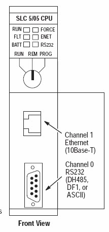
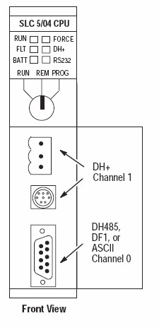
The SLC 5/03, SLC 5/04, and SLC 5/05 processors include a 3-position Key Switch on the front panel that lets you select one of three modes of operation: Run, Program, and Remote. You can
remove the key in each of the three positions.

Note : The SLC 5/01 and SLC 5/02 processors do not have a Key Switch. Therefore, all modes must be changed via the communication channels.


This position places the processor in the Run mode. The processor
scans/executes the ladder program, monitors input devices, energizes
output devices, and acts on enabled I/O forces. You can only change
the processor mode by changing the Key Switch position. You cannot
perform online program editing.
To change the processor mode to Run, toggle the Key Switch from
PROG or REM to RUN. When the Key Switch is left in the RUN
position, you cannot use a programmer/operator interface device to
change the processor mode.

PROG Position

This position places the processor in the Program mode. The
processor does not scan/execute the ladder program, and the
controller outputs are de-energized. You can perform online
program editing. You can only change the processor mode by
changing the Key Switch position.

To change the processor mode to Program, toggle the Key Switch
from REM or RUN to PROG. When the Key Switch is left in the
PROG position, you cannot use a programmer/operator interface
device to change the processor mode.

REM Position

This position places the processor in the Remote mode: either the
REMote Run, REMote Program, or REMote Test mode. You can
change the processor mode by changing the Key Switch position or by
changing the mode from a programmer/operator interface device.
You can perform online program editing in this position.
To change the processor mode to REM, toggle the Key Switch from
RUN or PROG to REM. When the Key Switch is in the REM position,
you can use a programmer/operator interface device to change the
processor mode.

Allen Bradley PLC Training in India


ALLEN BRADLEY PLC TRAINING IN NOIDA


ALLEN BRADLEY

MODEL NO: MICROLOGIX 1200 SERIES C
INPUT: 14 & OUTPUT: 10
COMMUNICATION PROTOCOL: RS 232

TO OPEN THE SOFTWARE


Then select CPU model 

 FILE – NEW – SELECT  (MICROLOGIX 1200 SERIESC)

Hardware configuration:


DIGITAL INPUT/DIGITAL OUTPUT (14/10):

INPUT:        I: 0/0    to   I: 0/13

OUTPUT:   O: 0/0   to   O: 0/9

INTEGER:  N7:0     N7:255

FLOAT:       F8:0    F8:255

BINARY:    B3:0/0        B3:0/15
                        .
                        .
                        .
                        .
                     B3:255/0    B3:255/15

CONTROL REGISTER: R6:0      R6:255

JUMP:          Q2:0   Q2:99

SUB ROUTINE: U:3     U:99

STRING:      ST9:0    ST9:255

ANALOG (2/2)

INPUT:         I:1.0 AND I:1.1
OUTPUT:     O:1.0 AND O:1.1

USER:
      NO CONTACT
      NC CONTACT
      LOAD
      LATCH COIL
      UN LATCH COIL


BIT:
1.ONE SHOT
2.ONE SHOT RISING
3.ONE SHOT FALLING
                                                                       
1.ONE SHOT:

It produces it pulse during off state to on state. It does not have output bit  
 
ONE SHOT RISING:
                                                 
It produces its pulse during of state to on state.

ONE SHOT FALLING:
    
It produces its output pulse during on state to off state   


Timer and Counter Instructions

If You Want to:                        Use This Instruction:
Delay turning on an output                         TON
Delay turning off an output                         TOF
Time an event retentively                            RTO
Count up                                                   CTU
Count down                                              CTD
Reset the accumulated value
and status bits of a timer or
counter.(Not used with
 TOF timers.)                                             RES       

    
COMPARE INSTRUCTION:


If You Want to                                      Use This Instruction

Test whether two values are equal (=)                                                 EQU
Test whether one value is not equal
 to a second value (><)                                                                        NEQ
Test whether one value is less than
 a second value (<)                                                                               LES
Test whether one value is less than
 or equal to a second value (<=)                                                           LEQ
Test whether one value is greater
 than a second value (>)                                                                       GRT
Test whether one value is greater
 than or equal to a second value (=>)                                                   GEQ
Test portions of two values to see
whether they are equal                                                                          MEQ
Test whether one value is within the
 limit range of two other values                                                              LIM       

 COMPUTE / MATH:

If You Want to                                                               Use This Instruction

Add two values                                                                         ADD
Subtract two values                                                                   SUB
Multiply one value by another                                                    MUL
Divide one value by another                                                       DIV
Change the sign of the source
 value and place it in thedestination                                             NEG

If You Want to                                                             Use This Instruction

Set all bits of a word to zero                                                       CLR
Convert an integer value to BCD                                                TOD
Convert a BCD value to an integer
 value                                                                                         FRD  


SQUARE ROOT (SQR):

Find the square root of a value        

GRAY CODED DECIMAL(GCD):
This output instruction converts the Gray code Source to integer and places it in the Destination. On a True rung, this instruction sets the value of the Destination to the integer value corresponding to the Gray code Source. If the Gray code input is negative (high bit set), the destination is set to 32767 and the overflow flag is set. The GCD instruction only operates on Word operands.      

 MOVE / LOGICAL INSTRUCTION:

If You Want to                                                                   Use This Instruction

Move the source value to the destination                                           MOV
Move data from a source location to a
selected portion of the destination                                                     MVM
Perform an AND operation                                                              AND
Perform an inclusive OR operation                                                   OR
Perform an Exclusive Or operation                                                   XOR
Perform a NOT operation                                                                NOT         

  MOVE:
When rung conditions preceding this instruction are true, the MOV instruction moves a copy of the source to the destination each scan. The original value remains intact and unchanged in its source location.

MASKED MOVE:
When rung conditions are true, the MVM instruction moves data from a source location to a destination, and allows portions of the destination data to be masked by a separate word. Data at the source address passes through the mask to the destination address. As long as the rung remains true, the instruction moves the same data each scan.

CLEAR:
When rung conditions are true, this output instruction sets all the bits in a word to zero. The destination must be a word address.

AND: When rung conditions are true, sources A and B of this output instruction are ANDed bit by bit and stored in the destination.

PROGRAM CONTROL:

If You Want to                                                                          Use This Instruction

Jump forward/backward to a
corresponding label instruction                                                          JMP, LBL
Jump to a designated subroutine and return                                     JSR, SBR, RET
Enable or inhibit a master control zone
 in your ladder program                                                                       MCR
Truncate program scan                                                                          TND

JUMP:
When the rung condition for this output instruction is true, the processor jumps forward or backward to the corresponding label instruction (LBL) and resumes program execution at the label. More than one JMP instruction can jump to the same label. Jumping forward to a label saves program scan time by omitting a program segment until needed. Jumping backward lets the controller execute program segments repeatedly.

JUMP TO SUBROUTINE:
When rung conditions are true for this output instruction, it causes the processor to jump to the targeted subroutine file. You can only jump to the first instruction in a subroutine. Each subroutine must have a unique file number (decimal, 3-255).   

  SUBROUTINE PAGE:

TO CREATE THE NEW SUBROUTINE PAGE:

PROGRAM FILES – RIGHT CLICK NEW


 TEMPORARILY END (TND):
Use this instruction to progressively debug a program, or conditionally omit the balance of your current program file or subroutines.

MASTER CONTROL RESET (MCR):
An input instruction is programmed on the rung of the first MCR to control rung logic continuity. When the rung goes "false" all non-retentive outputs within the controlled zone are disabled. When the rung goes "true" all rungs are scanned according to their normal rung conditions (disregarding the zone control instruction).


ADVANCED MATH INSTRUCTION:

If You Want to:                                            Use This Instruction:

Swap the low and high bytes
of a specified number of words                               SWP
Scale a value to a range determined
by creating a linear relationship                               SCP
Calculate the absolute value of a number                 ABS
Decoder functions                                                   DCD
Encoder function                                                     ENC


DECODER(DCD):

When rung conditions are true, the DCD instruction decodes a 4-bit value (0-16) in the source word and turns on a bit in the destination word that corresponds to the decoded value. For example, if bits 0-3 of a source word are 0110, then bit 6 in the destination word is set. The table below provides full details.

ENCODER (ENC):

This output instruction searches the source from the lowest to the highest bit and looks for the first set bit. The corresponding bit position is written to the destination as an integer.

SCALE WITH PARAMETER(SCL):

This output instruction consists of six parameters. Parameters may be integer, long, floating point (Floating point is only supported in the SLC 5/03, 5/04, and 5/05; not in the MicroLogix 1200 and 1500 processors.), or immediate data values or addresses containing values. The Input value is scaled to a range determined by creating a linear relationship between input min and max values and scaled min and max values. The scaled result is returned to the address indicated by the output parameter.

SWAP (SWP):
Use the swap instruction to swap the low and high bytes of a specified number of words in a bit, integer, ASCII, or string file. The instruction consists of two parameters, a source and a length.

ABSOLUTE VALUE (ABS):

This output instruction consists of two parameters, a source and a destination. When enabled it calculates the absolute value of the source and places the result in the destination.
Source can be a word address, an integer constant, floating point data element, or floating point constant. 
PLC SCADA Industry Oriented Courses at Sofcon

100% Placement Assiatance


PLC and SCADA are hardware and software related to automation of industrial processes.

Programmable Logic Controller or PLC is a computing system used to control electromechanical processes. It is designed for multiple input and output arrangements. It endures harsh environments and controls output for various devices such as displays, lights and valves.

 It is an example of hard real time system; the output results are produced in response to input within targeted time. PLCs are used to control machinery in factories, amusement parks, hospitals, hotels, military, traffic signals and construction.

SCADA stands for Supervisory Control and Data Acquisition. It is a type of industrial control system that is used to monitor and control facilities and infrastructure in industries. It is a means to develop conditions for managing processes and retrieve data in various scenarios. 

It is capable of handling large-scale processes involving multiple sites located far +off. The system is used in power generation and transmission, water treatment, gas transmission, fabrication, communication etc.

Training in PLC deals with programming micro-controllers using a specialised computer language. The course covers architecture, applications, instructions, interfaces and programmes of inputs and outputs of PLCs.

SCADA deals mainly with data acquisition and management. In SCADA training, you will learn to monitor the software and hardware used to communicate with the equipment on the field. Some topics covered in the training are applications of SCADA software, SCADA features, creating applications, creating database tags, developing graphic displays, trending, communication with PLC and other hardware, and commissioning of network nodes.

PLC and SCADA are advanced engineering subjects. Learning them demands hard work and patience.

Industries, big and small are increasingly getting automated.

They are using latest industrial automation technologies to deliver high quality products and services to their customers. So there is a need of qualified people who can handle the machinery and industrial processes. Getting trained at PLC and SCADA improves your career prospects.

To grow consistently in this field, you should have sound technical skills and keep updating yourself with the latest technological developments.

Sofcon Training Intitutes list in India Diffrent Cities.

Sofcon India Pvt Ltd PLC Training in noida and PLC Scada Training in Noida. Sofcon is group of companies since 1995 and Affiliate & Fundede by NSDC.

PLC Training in Delhi
PLC Training in Noida
PLC Training in Ghaziabad
PLC Training in Gurgaon
PLC Scada Training in Jaipur
PLC Training in Bhopal
PLC Training in Lucknow
PLC Training in Baroda
PLC Training in Rajkot
PLC Training in Ahmedabad
Autocad | Building Automation Training
Industrial Automation Solutions

PLC Updation | Vedanta to buy Cairn Energy Plc?

The murmur in Scotland is getting interesting.

Which is, according to The Scotsman, a respected daily in the region, that Cairn Energy Plc, the former parent company of Cairn India, may get taken over by the Anil Agarwal-controlled Vedanta Resources Plc.

While advice has been aplenty on how Cairn India should use its massive cash hoard, till late Monday evening, foreign media have been speculating about a possible takeover of Cairn Energy.
Media reports said Vedanta might unveil one of its most ambitious takeover programmes after announcement of its fourth quarter results on Wednesday.

“This will definitely be a good move by the group as it will not only give a global footprint to Cairn India but also give it access to an efficient team of Cairn Energy,” said Gagan Dixit, senior oil and gas analyst with brokerage Quant.

Cairn Energy, which still holds 10.27% stake in Cairn India, currently has 40 licences in the UK and Norway of which 5 wells are planned to be drilled in 2013.

Also, it has acreages in Greenland where it has already drilled 8 wells, 6 operated blocks offshore Morocco, 4 blocks in offshore eastern Spain and smaller assets in Malta, Ireland, France, Albania and Nepal.

Experts say currently Cairn Energy is available at cheaper valuations compared with its assets base and cash reserves and it is the right time for any company to make a bid for the same.

“The current share price is less than net cash plus the shares in Cairn India. In other words, the exploration portfolio is in for free,” said an analyst quoted in one of the international media reports.
Cairn Energy’s current market capitalisation stands at $2.6 billion, while its cash reserves ($1.6 billion) and its 10% holding in Cairn India add up to over $2.63 billion.

“It makes sense for Vedanta’s long term strategy and for increasing Cairn India’s influence across the world’s E&P portfolio, however it could be a little bad for the minority shareholders of Cairn India, who had been expecting some payback finally this year,” said an analyst with a domestic brokerage.

The analysts’ fraternity had been proposing a possible buyback also of Cairn India’s share as a best possible way for utilisation of its cash, as they it would also be value accretive for the company.

Source:-http://www.dnaindia.com/money/report-vedanta-to-buy-cairn-energy-plc-1820363

Wednesday 29 October 2014

Best Embedded System Training Institute


Sofcon embedded institute is a part of Sofcon India Pvt Ltd a company concerned in design, expansion & developing different electronic products catering a variety of applications in the marketplace. Sofcon Embedded Training Institute was established in the year 1995, since then the institute has trained thousands of students, who are now working in different levels in the Embedded System industry. We are training students as per the industry standards & work on the tools n techniques that are used to develop real embedded products & applications. Now we are one of the leading Embedded Systems Training Institute.


The majority of our training courses are Basic Embedded System, Advanced Embedded System, Post Graduate Diploma in Embedded Systems, We cover programming languages, design techniques, the newest infrastructure technologies and several courses designed to constantly improve your skills in the embedded environment.

Our Expertise:

Sofcon Centre of Excellence having a 18 years experience in embedded systems programming, therefore we have in-depth knowledge and hands on experience of all the issues you may be facing as an embedded software developer. 

Practical Experiences:

You learn from the company involved in developing the actual embedded products. This reassures you that you get the most practical knowledge. The skills sets that you acquire in Sofcon Embedded are readily related in the real world scenario.

Real world Experience: 

At Sofcon Centre of Excellence you will get a chance to work on the real product developments scenario. You will understand the practicalities while working on different tools & techniques. This will make you better equipped to handle the challenges, bugs, errors & difficulties that may happen in the development place of the company that you are employed in.

UpdatedSyllabus - Stay Ahead Of Times:
Every day the technologies are developed, the development techniques are improved upon, new IC’s are introduced and new coding patterns are developed. The companies that develop the real products are the one’s to use them at the latest. Later on it is passed on to the academic institutions, colleges & universities. So, by the time the knowledge is transferred to the students, the industry would have discarded the tools & technologies.

Excellent Team of Faculty & Mentors:
Training from Faculties with High level of Industry-Academia Exposure Mentoring from Industry Leaders & Technology Pioneers Further, there is active contribution of industry experts in providing subject insights and current trends. Expert guidance in the laboratory comes to the students, as Sofcon possesses qualified & committed manpower comprising of Doctorates, Professors & Researchers, Senior Programmers and Programmers.

Eligibility:

Eligibility: B.E / B.Tech / B.Sc / BCA / B.S with majors in Electronics / Computer Science or Related fields

Embedded Linux Training for Students in India

Title : Open “Embedded Linux” Software Development with
Date : 20th September 2008 (Saturday)
Venue : IISc, CEDT Seminar Hall, Bangalore


Registration : Free for First 100 members


TimeTopic
09:30 What, why, who, and how of open source
10:30 Quick overview of the Beagle Board
11:00 How does Beagleboard.org help students & startups in India
11:30 Break
12:00 Q &A and Discuss lab setup to boot Linux on beagleboard
01:00 Lab #1 (Build and Boot Linux)
01:45 Lunch
02:30 Validation Procedure for Peripherals on Beagle Board
03:00 Participating and Contributing to Open Community
04:00 Open discussion

Agenda:

  • Enable Students in India to develop s/w on embedded devices with Open Community.
  • Training students in using the embedded platform for s/w development
  • Give a big picture of what’s going on in the industry with Open Platforms.
  • Benefits of working with Open Community and beagleboard.org in particular.
Audience & expertise:

  • Students (2nd / 3rd year preferable) with very minimal knowledge of Linux,
  • Students who are passionate about Open Source Linux kernel and s/w development for embedded platforms.
Registration:

Enquiry For Embedded Training

Tuesday 28 October 2014

Coder's Corner: PLC Open Standards Architecture & Data Typing

Dr. Ken Ryan is a PLCopen board member and an instructor in the Center for Automation and Motion Control at Alexandria Technical College. He is the founder and director of the Manufacturing Automation Research Laboratory and directs the Automation Systems Integration program at the center.
 
This is the first in a series of articles focused on writing code using the IEC 61131-3 programming standard. The first few articles will focus on orientation to the architecture of the standard and the data typing conventions. After covering these, this series will explore code writing for a diverse field of application situations.
 
THE IEC 61131-3 SOFTWARE MODEL
 
Figure 1
 
The IEC 61131-3 standard has a hierarchal approach to programming structure. The software model in Figure 1 depicts the block diagram on this structure. Let’s decompose this structure from the top down.
 
Configuration:
 
At the top level of the software structure for any control application is the configuration. This is the “configuration” or the control architecture of the software defining the function of a particular PLC in a specific application. This PLC may have many processors and may be one of several used in an overall application such as a processing plant. We generally discuss one configuration as encompassing only one PLC but with PC-based control this may be extended to include one PC that may have the capability of several PLCs. A configuration may need to communicate with other configurations in the overall process using defined interfaces which provide access paths for communication functions. These must be formally specified using standard language elements.
 
Resource:
 
Beneath each configuration reside one or more resources. The resource supplies the support for program execution. This is defined by the standard as:
 
‘A resource corresponds to a “signal processing function” and its “man-machine interface” and “sensor and actuator interface” functions (if any) as defined in IEC 61131-3’.
 
An IEC program cannot execute unless loaded on a resource. A resource may be a runtime application existing in a controller that may exist in a PLC or on a PC. In fact, in many integrated development environments today, the runtime system can be used to simulate control program execution for development and debug purposes. In most cases a single configuration will contain a single resource but the standard provides for multiple resources in a single configuration. Figure 1 shows 2 resources under one configuration.
 
Task:
 
Tasks are the execution control mechanism for the resource. There may be no specifically defined task or multiple tasks defined for any given resource. If no task is declared the runtime software needs to have a specific program it recognizes for default execution. As you can see from Figure 1 tasks are able to call programs and function blocks. However, some implementations of the IEC 61131-3 standard limit tasks to calling programs only and not function blocks. Tasks have 3 attributes:
 
1.  Name
2.  Type – Continuous, Cyclic or Event-based
3.  Priority – 0 = Highest priority
 
The next article in this series will focus exclusively on tasks and their configuration and associations to programs and function blocks. For now we will continue our decomposition of the software model.
 
Program Organization Units:
 
The lower three levels of the software model are referred to collectively as Program Organization Units (POUs).
  • Programs
  • Function Blocks
  • Functions
Programs:
 
A program, when used as a noun, refers to a software object that can incorporate or ‘invoke’ a number of function blocks or functions to perform the signal processing necessary to accomplish partial or complete control of a machine or process by a programmable controller system. This is usually done through the linking of several function blocks and the exchange of data through software connections created using variables. Instances (copies of a program can only be created at the resource level. Programs can read and write I/O data using global and directly represented variables. Programs can invoke and exchange data with other programs using resource-level global variables. Programs can exchange data with programs in other configurations using communication function blocks and via access paths.
 
Function Blocks:
 
The real workhorses of this hierarchal software structure are the function blocks. It is common to link function blocks both vertically (one function block extends another) or horizontally (one function block invokes another) in order to create a well structured control architecture. Function Blocks encapsulate both the data (as internal variables and the input and output variable that interface the function blocks to other software objects) and an encoded algorithm that determines the value of internal and output variables based on the current value of input and internal variables. The key differentiator between function blocks and functions is the retention of values in memory which is unique to function blocks and not an attribute of functions. Since a function block can have a defined state by virtue of its memory, its class description can be copied (instantiated) multiple times. One of the simplest examples of a function block is a timer. Once the class object “timer” is described multiple copies of the class can be instantiated (timer1, timer2, timer3… etc.) each having a unique state based on the value of its variables.
 
Functions:
 
The ‘lowest’ level of program organization unit it the function. A function is a software object which when invoked and supplied with a unique set of input variables will return a single value with the same name and of the same data type as those of the function. The sine qua non of a function is the behavior that returns the same value anytime the same input values are supplied. The best example of a function is the ADD function. Any time I supply 2 and 2 to the ADD function inputs I will receive a 4 as the return value. Since there is no other solution for 2+2 then there is no need to store information about the previous invocation of the ADD function (no instantiation) and thus no need for internal memory.
 
Access paths:
 
The method provided for exchange of data between different configurations is that of access paths. Access paths supply a named variable that through which a configuration can transfer data values to/from other remote configurations. The standard does not define the lower layer protocol to be used for this transfer but rather defines the creation of a construct (‘container’) in which the data can travel.
 
Global Variable:
 

Finally we come to the variables which are declared to be “visible” to all members of a specific level on the hierarchy. If a global variable is declared at the program level then all programs, function blocks and functions that are members of this program have access to this data. We say that the data is within their scope. Likewise, a global variable declared at the resource level will be available to ALL programs located on this resource.

Source:-http://www.automation.com/library/articles-white-papers/programmable-control-plc-pac/coder146s-corner-plcopen-standards-architecture--data-typing

Databases – The Perfect Complement to PLC


PLCs? Okay, you’ve tackled PLCs and now you can program ‘em with one hand behind your back. So what’s next? What’s the next logical challenge? Think SQL and relational databases. Why? You’d be amazed the similarity. It’s the next logical progression.

You might ask how it is they’re even related. For one thing, relational databases can sort of be an extension of PLC memory. Live values can be mirrored there bi-directionally. Historical values and events can be recorded there as well. But operators and managers can interact with them too. It’s been over twenty years of working, living, breathing and thinking PLCs, but over the last six years I’ve delved heavily into SQL and learned a lot about relational databases. I’ve discovered that working with SQL is remarkably similar to working with PLCs and ladder logic.

SQL has four basic commands and about a hundred different modifiers that can be applied to each. These can be applied in various ways to achieve all types of results. Here’s an example. Imagine effluent from a wastewater plant with its flow, PH and other things being monitored and logged. That’s what you typically see. But now let’s associate other things with these, such as, discrete lab results, the name of the persons who did the lab work, the lab equipment IDs and calibration expiration dates, who was on shift at the time and the shift just prior, what their certification levels were, what chemicals where added and when, who the chemical suppliers were, how long the chemicals sat before use, and so forth ad infinitum. All of this becomes relational data, meaning that if it’s arranged properly in tables you can run SQL queries to obtain all types of interesting results. You might get insight into the most likely conditions which could result in an improper discharge so it can be prevented in the future.

In my explorations of SQL, I found myself looking at the layout of my tables and evaluating the pros and cons of each layout. I massaged them, turned them on their side, upside-down, and finally ended up with the most appropriate arrangement for my application. And similar to PLC programming, I explored innumerable what-if scenarios. I was struck by the amazing similarity in my approach to developing solutions for PLCs. This has been a lot of fun – in fact exhilarating – just like PLCs used to be. It’s the next logical progression you know.

SQL is a high level language that isn’t very hard to learn and you can be very clever with it. I prefer to think of it as a natural extension to my PLC programming skills. Now that you have the machinery running, what did it do? Furthermore, relational databases and SQL pull people and processes together. Machines don’t run alone. They’re merely part of a containing process and that process was devised by people. SQL and relational databases form the bridge to integrate processes, machinery and people together. I don’t believe a COTS (commercial-off-the-shelf) package can do it any more than you could offer a COTS palletizer program and have it be of any use. It just doesn’t work that way. Every machine is different. And every business process is different. That’s where the SQL comes in. It has to duplicate or augment existing process flows and these are intimately connected to the machinery. And that’s why the PLC programmer is best suited to implement solutions involving PLCs and relational databases.

So where do you start? I would suggest picking up a book at the bookstore like one of those dummies books. Then download and install the open-source MySQL database server along with the MySQL Administrator and Query Browser. It only takes a few minutes to install and then start playing. You can read about a LEFT JOIN or INNER JOIN but typing one in and observing the results is worth about 1000 words. At the end of an evening you’ll probably be very excited with all of your new found knowledge and be thinking of endless ways to employ it in your own field of practice. Happy SQLing!

Optimized Internet Protocol Network for Scada Systems

A. What is O-IP?

The basics of an O-IP system are to allow the use of Internet Protocol (IP) over narrow band systems with all the benefits of a licensed RF path. The data rates will be in the 4800 to 19200 bps range with a higher effective throughput. The O-IP product must be able to manage the Ethernet and IP packets such that only a minimum required amount of overheard information is sent through the air. The final O-IP product will manage both the amount of packet overhead sent over the air on the RF link and will also apply data compression algorithms to reduce the amount of user data sent.


B. Why an Optimized Internet Protocol Device?

Why is there a need for Optimized Internet Protocol (O-IP) communications? The Supervisory Control and Data Acquisition (SCADA) industry is moving toward the Internet Protocol (IP) enabled network in a very determined manner. There are several reasons: the need for network manageability; the movement of manufacturers to IP based products, the general movement away from serial connections and the fact that many SCADA systems and automation groups have been moved into existing Networking control groups or Information Technology (IT) organizations.

Greater distance Radio Frequency (RF) paths are achieved with narrow band Frequency Modulated (FM) licensed products. Since the frequencies are licensed and regulated, power amplifiers and specialized RF filtering products can be used to give system reliable spans measured in tens of miles, not just miles. It is not atypical for a narrow band Ultra High Frequency (UHF) SCADA system to cover 50 or 75 miles of territory with no repeaters or single systems. Some Very High Frequency (VHF) based systems reach in excess of 90 miles as a routine design requirement. The fact that the frequencies are assigned by a governing agency (Federal Communications Commission) and coordinated by local frequency coordinators also give a certain level of certainty that interference will be less likely and there is some recourse should it occur. This is not necessarily a feature of typical wide-band unlicensed products. The FCC Part 15 devices (spread spectrum) are required to "co-exist" with any interference and it is not uncommon that a move to a licensed frequency alleviates interference problems.

The movement away from RS-232 serial communications methods poses challenges. There is a significant installed base of serial-based Integra communications systems working on narrow band (25 kHz and 12.5 kHz channels). These systems are typically slow to mid-speed (1200-19200 bits per second (bps)) applications. It was not too long ago 9600 or 19200 bps was considered very fast in the SCADA business! There is also a large installed base of serial based Integra spread spectrum products. In either case, the wholesale replacement in terms of cost, downtime and staff time is appreciable and they make alternatives worth looking at.


C. How Will O-IP Work?

A typical Ethernet message consists of a lot of overhead information to make sure the data arrive at their intended destination. However, if the design of the network is known, a certain amount of that header information can be limited, lowering the on-air traffic.

Typical Ethernet User Datagram Protocol (UDP) or Transmission Control Protocol /IP (TCP/IP) Overhead:
In many cases the overhead can exceed the actual SCADA message, i.e., a 54-byte header to send a 6-byte SCADA message. This would not be an acceptable or efficient method of SCADA communications.

Dataradio's mobile VIS (Vehicular Information System) optimized IP product has been in service for sometime now. It has been deployed in many locations with strong success. Taking lessons from that product development, Dataradio Engineering developed a SCADA Optimized IP solution that focuses on the particular needs of the SCADA user for IP connectivity.

The requirement for duplicate packets generated by TCP/IP are significantly reduced. Customized Data Compression algorithms afford up to a 50% compression rate for data, dependent on the data type. Header reduction is a fixed reduction of 25%.
This type of network intelligence is designed into a small microprocessor board that will be available as an add-on enclosure (Phase One) and an integral (Phase Two) with Dataradio products. There will not be a need for a separate personal computer or server in the system. Set up will be via personal computer and a table file structure and/or command line/HTTP based interface.

When there is high bandwidth/short distance available, a Media Access Control (MAC) layer bridge with little or no filtering may work well. Inefficiencies in data transmission are compensated for with the higher speed of such a link. However, if a similar approach is taken over a narrow band FM RF link, performance will not be sufficient to allow acceptable operation. This is where the Optimized IP connection methodology is best utilized, allowing a reasonable connection in these cases.

Remote Terminal Unit (RTU) Test Set-up:
Figures 1 and 2 are diagrams that outline two test set-ups that were used to verify and test the operation of the O-IP device. Test set-ups were based on user feedback as to the type of possible networks. Other connections are likely however these two test scenarios represent how we would expect the product to be put into service on an initial basis. Additional addressing data is provided to indicate the set-up format.


Figure 1: Test RTU Network Setup:


Figure 2: IP Native RTU and Terminal Server Network


D. What Are Some System Design Considerations of an O-IP System?

System design criteria requires some up-front work, especially since there are not unlimited speed and bandwidth allocations. SCADA system design is not foreign to SCADA users, however, with Local Area Network (LAN) systems a larger amount of the system "design" is left to the equipment and less than optimal designs can be compensated for by the high throughput enjoyed in LAN type systems. Some design criteria are listed below:
  1. These SCADA O-IP systems will not support web surfing. Email systems such as Outlook and Lotus Notes will not be efficient because of the half-duplex nature of the radio channel and full-duplex nature of TCP. The overhead is simply too large and the system responsiveness would likely not be acceptable. A simple text based email system would work if not overused. Drive sharing and other common network components will not function well.
  2. Efficient data throughput is based on SCADA oriented messaging size. Structures of the SCADA messaging need to be understood and perhaps adjusted to fit the application. Throughput is based on application architecture; i.e., half-duplex or full-duplex, number of devices supported and message size. This is in effect no different than what is currently done for serial based systems.
  3. Rockwell Automation offers the following advice: "The recommended Ethernet/IP network topology for control applications is an active star topology (10 MBPS and 100 MBPS Ethernet can be mixed) in which groups of devices are point to point connected to a switch. The switch is the heart of the network system." O-IP is closer to a WAN environment, an Ethernet switch (star topology) is used for deterministic networks and deterministic response times while a WAN tends to be designed for more flexible approach to data movement. The O-IP environment allows for the chance of a data collision unless a polling-based application is used - this is a more typical SCADA application. In this type of optimized system, the routing and gateway capabilities of O-IP are utilized to better manage on-air RF traffic and maintain system reliability - we need to work smarter not merely faster.
  4. Dynamic Host Configuration Protocol (DHCP) will not be supported in the initial offering. Design requirements should limit any application protocol based on IP broadcasting. We recommend using multicasting instead. There has not been a strong requirement indicated for this feature which can create significant overhead. The system has to be laid out with as much determinism as possible. If elements are changed, then the tables get changed. Typically SCADA systems have minimal change so change control can be implemented and table up-dates managed. Simply stated, SCADA systems are typically static address based.
  5. The O-IP product will function as a gateway and router intelligently limiting the amount of traffic it forwards on to the RF network. As a comparison, MAC layer bridging would forward all broadcast messages generated on local LAN; i.e., IP broadcast, Internet Packet exchange (IPX) broadcast would forward Address Resolution Protocol (ARP) requests over the RF channel.
  6. There is no limit on the number of Remote Terminal Units (RTU)/Programmable Logic Controllers (PLC) but network latency is dependent upon the number of RTU/PLCs on the network. Most serial systems require some kind of traffic calculation/review to determine how many sites can be polled and respond within a given time frame. Most network administrators and vendors have tools that assist in calculating the system latency, throughput and scan rates. Dataradio provides at least two types for general rule-of-thumb use. System designers may need to work with system programmers to understand data structures and required throughput rates for the application. This may also involve the process control/system engineers to understand what overall system performance criteria are. It has been the experience of Dataradio Technical Services that when these items are not addressed, system performance is not optimal either serial communications or LAN. There are networking tools available to assist in system performance evaluation and some allow for system performance extrapolation. Parameters such as tuning of TCP/IP parameters (Maximum Transmission Unit (MTU) size, MSS size etc.) will need to be set correctly. Dataradio will publish starting benchmarks for these parameters as work progresses with more systems and products.
  7. How will the SCADA network be linked to any other corporate networks - through hubs or switches? How will the demands for non-SCADA information be handled? Tight control needs to be exercised or random data requests could easily impact the basic system performance. Requests addressed to RTUs/PLCs/Intelligent Electrical Devices (IED) will be passed on but if those requests come from a non-SCADA application (Engineering, Accounting, and Maintenance) the amount of traffic can impact system performance. Understanding how broadcast messages move through the system is important. O-IP will have the capability to enable or disable broadcast IP messages in the O-IP set-up. Limiting the number of broadcasts will keep traffic levels down as well.
  8. System addressing needs to be thought out in advance to avoid duplicate addresses and use of illegal addresses. If the SCADA networks are kept isolated from other networks private IP addresses can be used for RTU/PLCs.
  9. What types of devices will be on the network? RTUs, PLCs, IEDs, terminal servers, meters and other process control devices (virtually any device that uses IP as a network layer) can be used with O-IP. Each type of device has a communication profile that needs to be taken into account as far as messaging size, latency control, reply message size and ad-hoc messaging. Network dynamic control is a part of future Dataradio O-IP work.
    If the system is a class C network, up to 254 devices could be on the segment. But having a device count capability is not the same as having the throughput capability. If all the messaging is small and short, 254 devices could easily be supported. What it really gets down to is this: The more points there are to monitor, the longer it will take the system to poll them. Network latencies will impose longer scan times on data collection routines.
  10. What protocols can be used with an O-IP system? Protocols such as UDP, TCP, Internet Control Message Protocol (ICMP), ARP, Modbus/IP (IP and a Modbus header), Modbus/TCP, ASCII over IP, Distributed Network Protocol (DNP) 3.0 are supported (timing constraint issues have come up with DNP 3.0 in any number of applications- not just O-IP. Review of the application and latencies is necessary.
    A.  Items that should be reviewed are:
    1. What is a typical data request size?
    2. What is the typical data reply payload size?
    3. What latencies are allowed by the PLC/IED/RTU?
    4. Will LAN system latencies work with RF system latencies? (The longest latency will govern the system performance).
    5. A review of timing requirements for the SCADA host program needs to include timing for message turn-around, message reply timer, total message timer, and other system timers.
    6. Does the design of the network and other network devices allow for longer latencies inherent in an RF system? Some devices internally buffer data to avoid latency time issues; others allow a longer latency.
  11. Once network design issues are addressed, full system design can be completed and implementation can go forward. Progressive system testing should be performed so that issues can be addressed and resolved in smaller groups as opposed to turning the entire system on and then trying to "whittle down" issue areas.
  12. Most end users tend to use a few protocols, devices and designs. Once this effort is done for the first system, a lot of the information will be able to be transferable for use in other systems. These elements are also part of any design effort for maximized system operation. These efforts are often the difference between a marginally operating and a truly efficient system.


E. Conclusion:

O-IP has a place in the RF market, especially supporting the narrow band FM sector. It represents a significant step forward allowing a greater connectivity option for those users who are distance constrained and want to use their legacy Integra installations. It also provides a migration path that will minimize the cost of conversion to a more manageable level.

Used in conjunction with the Integra wireless modem, the full feature set of the Integra system is available to the user. This includes online, offline and remote diagnostics, plus Dataradio infrastructure products, base stations, repeaters, rack mounting, power supplies, power amplifiers, antenna kits, National Electrical Manufacturers Association (NEMA) enclosures and High Availability (redundant bases and repeaters) options. The High Availability option allows for a "no single point of failure" system-back up capability for those critical links that need guaranteed uptime.

The product will be available initially as an add-on product, allowing for maximum up-grade flexibility. However, the end user will need to do some up-front work to take as full advantage of the capabilities. In many cases this information should (generally) be available as normal system design or maintenance information. The end user has the responsibility of managing the network for maximum performance, understanding that O-IP is not a panacea for all IP network needs but a targeted answer for certain needs.


Notes

  1. All respective trade names trademark, copyrights, and service marks are property of their respective owners.
  2. The use of a trade name or product name does not necessarily constitute an endorsement of that product, device, or software.

This article was written and provided by Harry Ebbeson, Manager of Technical Services at Dataradio COR Ltd. Dataradio is a leading designer and manufacturer of advanced wireless data products and systems for mission critical applications.

Source:-http://www.automation.com/library/articles-white-papers/hmi-and-scada-software-technologies/optimized-internet-protocol-network-for-scada-systems