Showing posts with label plc training. Show all posts

Wednesday 29 November 2017

What is PLC? - A Beginner's PLC Overview Every PLC Beginner Should Know

This blog post is for beginners who are interested in learning about PLC and SCADA, but they are confuses or not sure where to start. After read this post you will be able to identify the most basic components of a PLC system and can also know about the basic purpose and function of PLCs (and PACs). In this post I have cover all the basic about PLCs (and PACs).

What is PLC?

PLC stands for Programmable Logic Controller or programmable controller are small industrial digital computers which have modular components designed to control the manufacturing processes. PLCs are often used in factories and industrial plants to control light, motors, fans, pumps, circuit breakers and any other activity that requires high reliability control and ease of programming and process fault diagnosis. To understand the purpose of PLCs better, let’s look at a brief history of PLCs.

History of PLC-

Industrial automation started well before PLCs. In the right on time to mid 1900s, automation was typically done utilizing muddled electromechanical communicate circuits. Be that as it may, the measure of relays, wires and space expected to make even straightforward automation was risky. A large number of relays could be important to robotize a basic industrial facility process! Furthermore, if something in the intelligent circuit should have been changed?

In 1968 the first programmable logic controller came along to substitute complex transmit circuitry in industrial plants. The PLC was intended to be effortlessly programmable by plant architects and specialists that were at that point acquainted with transfer rationale and control schematics. Since the starting PLCs have been programmable utilizing stepping stool rationale which was intended to imitate control circuit schematics. The stepping stool graphs look like control circuits where control is spilling out of left to directly through shut contacts to empower a hand-off loop.

In the above diagram, you can see ladder logic looks like simple control circuit schematics where input sources (switches, push-buttons, proximity sensors, etc) are shown on the left and output sources are shown on the right.

How Do PLCs Work?

There are many PLCs components, but only these below three are most important of them:

  1. Processor (CPU)
  2. Inputs
  3. Outputs

PLCs are most complicated and powerful digital computers but here we can describe the function of a PLC in simple terms. The PLC takes inputs & performs logic in the CPU and then turns on or off outputs based on that logic.

  1. The CPU monitors the status of the inputs (ex. switch on, proximity sensor off, valve 40% open, etc.)
  2. The CPU takes the information that it gets from the inputs, performs logic on the inputs
  3. The CPU operates the outputs logic (ex. turn off motor, open valve, etc.)

See the flowchart below for a visual representation of the steps above.


Conclusion: Now you have better understanding of what PLCs are and how they work. Now you can start your PLC course. This was basic concept and was most important to know before start PLC training.

Saturday 10 June 2017

The future of Industrial automation PLC SCADA technologies

Every industrial automation PLC SCADA project starts with the familiar process of counting I/O, selecting vendors, laying out PLC chassis, and distributing requests for quotes. And finally you are commissioning a system built on general standards, repeating the same mistakes as previous systems.

The conversations also repeat during bid review or negotiation meetings when someone points out inconsistent or outdated standards. Technology is changing so fast, and the past few years have brought technical advances that have breathed new life into Industrial automation groups and started great discussions around what the future holds. There is still a lot of work to be done.


Virtualization is a great example. Early adopters saw the benefits, and news spread like wildfire. As SCADA (supervisory control and data acquisition), manufacturing execution systems, and historian capabilities increased, so did the need for processing power, and virtualization was the perfect answer. Virtualization is now commonplace in Industrial automation domain. And many are asking what is next. The next big thing is waiting to happen. Industry has become more demanding asking for virtualized controllers and solution with mobility. But they are easily feasible with existing technology. The success of our industry depends on it.

HMI/PLC SCADA industrial automation applications have already secured their place as key components for any smart factory, IT-focused applications. Humans by nature are reluctant to give up control; however, fully automated facility does not mean a complete end of human interference on the factory. Considering the huge focus in industrial automation / automated equipment and intelligent HMI/PLC SCADA software, it is important that manufacturers invest in employee training, enabling talented engineers from industrial automation domain to focus on important tasks. 

NOIDA - 9873630785, Delhi - 9873630783, GURGAON - 9873588305, LUCKNOW - 9838834288, ALLAHABAD - 7704003025, JAIPUR - 8058033551, MOHALI - 9873349806, BHOPAL - 755-4002787, VADODARA - 9898666980, AHMEDABAD - 9227185900, PUNE - 7387700933

Wednesday 19 November 2014

Indutarial Summer Training in Noida PLC Scada Embedded Systems Autocad Solid Works Primavera Catia Staad Pro Course


About Sofcon: - 
Sofcon India Private Limited is a Pioneer Institute in the Field of Automation and Industrial Training for Technical Aspirants since 1995. We are now affiliated and Funded by National Skill Development Corporation (NSDC) set up by the Ministry of Finance (Government of India) with a mission of 100,000 Placements till 2020.
Sofcon is an ISO 9001:2008 Certified company and System Integrated for Industrial Automation for Schneider Electric and ABCS(Authorized Building Controls Specialist) for Johnson Controls, We believe in Quality and delivering Excellence, We are working towards bridging the gap between Academics and Industrial requirements from more than last 2 Decades.
Sofcon institute have different branches across India to provide Quality teaching to technical students. At present Sofcon has following Centers across the country as mentioned below:-
1.Noida Sector-2(UP)
2.Noida Sector-6(UP)
3.Delhi
4.Gurgaon(Haryana)
5.Lucknow(UP)
6.Bhopal(MP)
7.Rajkot(Gujarat)
8.Baroda(Gujarat)
9.Ahmadabad(Gujarat)
10.Jaipur(Rajasthan)
About NSDC: - 
NSDC stands for National Skill Development Corporation set up by the Ministry of Finance, Government of India. NSDC is one of its kinds a PPP (Public Private Partnership) not-for-profit company. NSDC was set up with a mission to upgrade the skills of manpower in India, focusing on different sectors such as Electronics, IT and Hardware, Agriculture, Automotive, Construction, Leather, Plumbing, Retail, Security and many more. Sofcon is Affiliated with NSDC covering Electronics Skills Sector.
Courses Offered by Sofcon: - At present Sofcon offers following courses with 100% Job Assistance.
1.)Engineering Courses:-
a)Industrial Automaton Engineer(For B.Tech./B.E./Diploma in Electronics/Electronics and Communication/Electrical/Electrical and Electronics/Industrial Engineering)
b)Building Automation Engineer(For B.Tech./B.E./Diploma in Mechanical/Automobile/Electronics/ Communication/Electrical /Industrial Engineering)
c)Embedded System Engineer(For B.Tech./B.E./Diploma in Electronics/Electronics and Communication/Electrical/Electrical and Electronics/Industrial Engineering)
2.)Technician Courses:-
a)Access Controls Installation Technician(For ITI/Diploma in any Stream)
b)Site Engineer-Control Panel(For ITI/Diploma in Electrical/Mechanical Eng.)
c)CCTV Installation Technician(For ITI/Diploma in any stream)
d)Maintenance Technician Electrical(For ITI/Diploma in any stream)
e)Electrical Assembly Operator(For 10th/12th/ITI/Diploma Students)
f)Wireman Control Panel(For 10th/12th/ITI/Diploma Students)
About Industrial Automation Engineer: - Industrial Automation Engineers design, program, simulate and test automated machinery and processes in order to complete exact tasks. They are responsible for proper working of the systems under their observations at peak efficiency in the Industries. They have to work in the controls and automation industry and are in charge of automating and manufacturing processes.
Course Contents of Industrial Automation Engineer:-This course covers Programmable Logic Controllers (PLC), Supervisory Control & Data Acquisition (SCADA), Human Machine Interface (HMI) & Variable Frequency Drives (VFD) etc. These systems fall squarely in the Industrial Electronics domain. These systems are employed by the manufacturing sector and need engineering personnel for operation, maintenance, design, implementation and augmentation.
Career for Industrial Automation Engineer: - There are a number of opportunities waiting for an Automation Engineer within India and across the globe. As the job profile is completely based on industrial requirements, there is a good opportunity for an individual having knowledge and a job role of Industrial Automation Engineer.
There are a number of Automation companies for placements such as JCT Electronics, Bajaj, Motherson Ltd, ABB, Samsung, Emerson, Omron and many more.
About Building Automation Engineer: - Building Automation Engineer is responsible for the design of building automation systems using company tools and operating protocols. The individual at work needs to control and supervise microprocessor and microcontroller based automated systems, it includes Fire Detection & Alarm System (FAS), Access Control Systems, Biometrics (ACS) & CCTV Surveillance Systems along with a variety of Sensors and actuators. The individual at work is responsible to supervise the installation and maintenance of automation systems that control such features as lighting, temperature, water heating etc. Job duties include providing cost estimates, designing and wiring systems, checking software parameters, and training personnel in the use of systems. Building automation engineers must have the ability to work with CAD software to design system schematics and must be comfortable with HVAC systems.
Course Contents of Building Automation Engineer: - This course covers Building Automation Systems comprising Direct Digital Controllers (DDC), Microprocessor based Fire Detection & Alarm System (FAS), Access Control Systems, Biometrics (ACS) & CCTV Surveillance Systems along with a variety of Sensors and actuators. These systems are employed and embedded within all Infrastructure like Metros, Airports, Buildings, Environmentally sensitive locations like Pharmaceutical & Food plants, Hospitals, Chip fabs etc and Building Automation Engineers are required for operation, maintenance, design, implementation and augmentation of these systems.
Career for Building Automation Engineer: - As the need of construction and safety is increasing every day, the requirement of automated buildings is raised so there are huge opportunities waiting for a candidate with similar job profile. There are a number of companies in which Building Automation Engineer can be placed such as Campbell, Rockwell Automation, Johnson Controls, Schneider, Pepsico, JP group, Honeywell and many more.
About Embedded System Engineer: - Embedded Software Engineer has to execute complete embedded software development lifecycle. The goal is to create scalable and optimized software and hardware systems. The individual at work is responsible to Design and implement software of embedded devices and systems from requirements to production and commercial deployment. He have to Design, develop, code, test and debug system software as well as Hardware.
Course Contents of Embedded Systems Engineer: - This course covers microcontrollers (8051, ARM, PIC, AVR) along with a variety of Sensors and actuators. We also cover Real Time Operating Systems (RTOS) besides Embedded C. These systems are employed and embedded within all electrical and electronic durable equipment and Embedded Systems Engineers are required for operation, maintenance, design, implementation and augmentation of these systems.
Career for Embedded Systems Engineer: - Embedded System Engineers can start their career in core electronic companies such as Samsung, LG, Motorola, Nokia, Siemens, Mitsubishi, HCL, BEL, Ericson and many more.
About Access Controls Installation Technician Course: - The Access Control Installation Technician provides after sale support services for access control devices and systems such as point of sale scanners, finger print or iris scan etc. He is responsible for installing the access control system at the customer's premises. The individual undertakes site assessment, installs the hardware and integrates the system to meet customer's requirement. The course contents are Installing and setup the access controls systems, engage with customer for installation. The individuals can be placed in the companies installing and commissioning Access controls systems.
About Site Engineer Control Panel Course: - The Site Engineer provides after sales support and is responsible for installing and commissioning the control panel at customer's site. The individual at work is responsible for installing the control panel at customer site and ensure its operation on being powered up. The individual must: have the ability to work in high-decibel noise environment, lift heavy objects and work in a standing position for long hours.
About CCTV Installation Technician Course: - The CCTV installation Technician provides after sale support services to customers, typically, at their premises. The individual at work is responsible for installing the CCTV system in the customer premises. The individual understand the customer and site requirement, installs the camera and integrates the hardware for effective CCTV surveillance system functioning. The job requires the individual to have ability to build interpersonal relationships, patience, listening skills and critical thinking. The individual must be willing to travel to client premises in order to install equipment at different locations.
About Maintenance Technician Electrical Course: - Individuals at this job are responsible for maintaining the Electrical/ electronic systems of equipment and machinery. They use laid down procedures, and knowledge of the equipment to conduct routine maintenance and organize repairs. They are also involved in control and monitoring devices and occasionally in the manufacture of items that will help in maintenance.
About Electrical Assembly Operator Course: - The Electrical Assembly Operator is responsible for make electrical connections of control panel assembly. The individual at work mounts and installs and connects internal electronic modules devices and components on the control panel.
About Wireman Control Panel Course: - The Control Panel Wireman reads the wiring diagram and routes and wires various components within the panel in accordance to the diagram. The individual at work is responsible for wiring all components present within the panel as per specifications provided by the design engineering team.

Source:-http://goarticles.com/article/Indutarial-Summer-Training-in-Noida-PLC-Scada-Embedded-Systems-Autocad-Solid-Works-Primavera-Catia-Staad-Pro-Course/9732814/

Friday 14 November 2014

How to Make Start Stop Logic in PLC using Different NO-NC Combination

This Tutorial Will teach you how to use NO and NC for making Start stop logic. For this we understand that you have basic knowledge of No and NC . You can also learn Basic of PLC here.

To make start-stop logic you just have to write a simple program in PLC. In Electrical it is possible to make start – stop logic with a NO start push button and NC stop push button BUT in PLC you can make start-stop logic with any combination of start and stop push button.

Let us understand ……..

**PB- Push Button, NO – Normally Open, NC – Normally Closed**

1> Start PB – NO , Stop PB – NC


2> Start PB – NO , Stop PB – NO


3> Start PB – NC , Stop PB – NO


4> Start PB – NC , Stop PB – NC


Source:-http://www.automation-talk.info/2010/07/how-to-make-start-stop-logic-in-plc.html

Basic PLC Program

Input signal from Input device will entrance to PLC by Input module. After that PLC will process Input signal with Processor memory. Then PLC will transfer Output signal to Output device by Output module.


PLC

Basic componant of PLC Programs .

1. CPU ( Central Processor Module )
Process software application in ROM/RAM. Some application depend on Brand or Type.

2. Memory Unit
- ROM : Storage functions of the PLC Programs, Have battery to back up.
- RAM : Can be divided into EPROM, which will require special equipment to write and delete

3. I/O Unit
- Digital input module : Receive digital signal from Input device. ( 24VDC/VAC, 110V, 220V )
- Digital output module : Send digital signal to Output device. ( 24VDC/VAC, 110V, 220V )
- Analog input modle : Receive analog signal from Input device. ( 0-10VDC, 4-20Ma )
- Analog output module : Send analog signal to Output device. ( 0-10VDC, 4-20Ma )

4. Power supply
To supply electricity to PLC Program device.

5. Base module
To connect all PLC Programs device.

Thursday 30 October 2014

PLC SCADA Industry Oriented Courses at Sofcon

100% Placement Assiatance


PLC and SCADA are hardware and software related to automation of industrial processes.

Programmable Logic Controller or PLC is a computing system used to control electromechanical processes. It is designed for multiple input and output arrangements. It endures harsh environments and controls output for various devices such as displays, lights and valves.

 It is an example of hard real time system; the output results are produced in response to input within targeted time. PLCs are used to control machinery in factories, amusement parks, hospitals, hotels, military, traffic signals and construction.

SCADA stands for Supervisory Control and Data Acquisition. It is a type of industrial control system that is used to monitor and control facilities and infrastructure in industries. It is a means to develop conditions for managing processes and retrieve data in various scenarios. 

It is capable of handling large-scale processes involving multiple sites located far +off. The system is used in power generation and transmission, water treatment, gas transmission, fabrication, communication etc.

Training in PLC deals with programming micro-controllers using a specialised computer language. The course covers architecture, applications, instructions, interfaces and programmes of inputs and outputs of PLCs.

SCADA deals mainly with data acquisition and management. In SCADA training, you will learn to monitor the software and hardware used to communicate with the equipment on the field. Some topics covered in the training are applications of SCADA software, SCADA features, creating applications, creating database tags, developing graphic displays, trending, communication with PLC and other hardware, and commissioning of network nodes.

PLC and SCADA are advanced engineering subjects. Learning them demands hard work and patience.

Industries, big and small are increasingly getting automated.

They are using latest industrial automation technologies to deliver high quality products and services to their customers. So there is a need of qualified people who can handle the machinery and industrial processes. Getting trained at PLC and SCADA improves your career prospects.

To grow consistently in this field, you should have sound technical skills and keep updating yourself with the latest technological developments.

Sofcon Training Intitutes list in India Diffrent Cities.

Sofcon India Pvt Ltd PLC Training in noida and PLC Scada Training in Noida. Sofcon is group of companies since 1995 and Affiliate & Fundede by NSDC.

PLC Training in Delhi
PLC Training in Noida
PLC Training in Ghaziabad
PLC Training in Gurgaon
PLC Scada Training in Jaipur
PLC Training in Bhopal
PLC Training in Lucknow
PLC Training in Baroda
PLC Training in Rajkot
PLC Training in Ahmedabad
Autocad | Building Automation Training
Industrial Automation Solutions

PLC Updation | Vedanta to buy Cairn Energy Plc?

The murmur in Scotland is getting interesting.

Which is, according to The Scotsman, a respected daily in the region, that Cairn Energy Plc, the former parent company of Cairn India, may get taken over by the Anil Agarwal-controlled Vedanta Resources Plc.

While advice has been aplenty on how Cairn India should use its massive cash hoard, till late Monday evening, foreign media have been speculating about a possible takeover of Cairn Energy.
Media reports said Vedanta might unveil one of its most ambitious takeover programmes after announcement of its fourth quarter results on Wednesday.

“This will definitely be a good move by the group as it will not only give a global footprint to Cairn India but also give it access to an efficient team of Cairn Energy,” said Gagan Dixit, senior oil and gas analyst with brokerage Quant.

Cairn Energy, which still holds 10.27% stake in Cairn India, currently has 40 licences in the UK and Norway of which 5 wells are planned to be drilled in 2013.

Also, it has acreages in Greenland where it has already drilled 8 wells, 6 operated blocks offshore Morocco, 4 blocks in offshore eastern Spain and smaller assets in Malta, Ireland, France, Albania and Nepal.

Experts say currently Cairn Energy is available at cheaper valuations compared with its assets base and cash reserves and it is the right time for any company to make a bid for the same.

“The current share price is less than net cash plus the shares in Cairn India. In other words, the exploration portfolio is in for free,” said an analyst quoted in one of the international media reports.
Cairn Energy’s current market capitalisation stands at $2.6 billion, while its cash reserves ($1.6 billion) and its 10% holding in Cairn India add up to over $2.63 billion.

“It makes sense for Vedanta’s long term strategy and for increasing Cairn India’s influence across the world’s E&P portfolio, however it could be a little bad for the minority shareholders of Cairn India, who had been expecting some payback finally this year,” said an analyst with a domestic brokerage.

The analysts’ fraternity had been proposing a possible buyback also of Cairn India’s share as a best possible way for utilisation of its cash, as they it would also be value accretive for the company.

Source:-http://www.dnaindia.com/money/report-vedanta-to-buy-cairn-energy-plc-1820363

Monday 27 October 2014

PLC | The Future of Industrial Automation

 PLC Training


Since the turn of the century, the global recession has affected most businesses, including industrial automation. After four years of the new millennium, here are my views on the directions in which the automation industry is moving.

The rear-view mirror

Because of the relatively small production volumes and huge varieties of applications, industrial automation typically utilizes new technologies developed in other markets. Automation companies tend to customize products for specific applications and requirements. So the innovation comes from targeted applications, rather than any hot, new technology.

Over the past few decades, some innovations have indeed given industrial automation new surges of growth: The programmable logic controller (PLC) – developed by Dick Morley and others – was designed to replace relay-logic; it generated growth in applications where custom logic was difficult to implement and change. The PLC was a lot more reliable than relay-contacts, and much easier to program and reprogram. Growth was rapid in automobile test-installations, which had to be re-programmed often for new car models. The PLC has had a long and productive life – some three decades – and (understandably) has now become a commodity.

At about the same time that the PLC was developed, another surge of innovation came through the use of computers for control systems. Mini-computers replaced large central mainframes in central control rooms, and gave rise to "distributed" control systems (DCS), pioneered by Honeywell with its TDC 2000. But, these were not really "distributed" because they were still relatively large clumps of computer hardware and cabinets filled with I/O connections.

The arrival of the PC brought low-cost PC-based hardware and software, which provided DCS functionality with significantly reduced cost and complexity. There was no fundamental technology innovation here—rather, these were innovative extensions of technology developed for other mass markets, modified and adapted for industrial automation requirements.

On the sensor side were indeed some significant innovations and developments which generated good growth for specific companies. With better specifications and good marketing, Rosemount's differential pressure flow-sensor quickly displaced lesser products. And there were a host of other smaller technology developments that caused pockets of growth for some companies. But few grew beyond a few hundred million dollars in annual revenue.

Automation software has had its day, and can't go much further. No "inflection point" here. In the future, software will embed within products and systems, with no major independent innovation on the horizon. The plethora of manufacturing software solutions and services will yield significant results, but all as part of other systems.

So, in general, innovation and technology can and will reestablish growth in industrial automation. But, there won't be any technology innovations that will generate the next Cisco or Apple or Microsoft.

We cannot figure out future trends merely by extending past trends; it’s like trying to drive by looking only at a rear-view mirror. The automation industry does NOT extrapolate to smaller and cheaper PLCs, DCSs, and supervisory control and data acquisition systems; those functions will simply be embedded in hardware and software. Instead, future growth will come from totally new directions.

New technology directions

Industrial automation can and will generate explosive growth with technology related to new inflection points: nanotechnology and nanoscale assembly systems; MEMS and nanotech sensors (tiny, low-power, low-cost sensors) which can measure everything and anything; and the pervasive Internet, machine to machine (M2M) networking.

Real-time systems will give way to complex adaptive systems and multi-processing. The future belongs to nanotech, wireless everything, and complex adaptive systems.
Major new software applications will be in wireless sensors and distributed peer-to-peer networks – tiny operating systems in wireless sensor nodes, and the software that allows nodes to communicate with each other as a larger complex adaptive system. That is the wave of the future.

The fully-automated factory

Automated factories and processes are too expensive to be rebuilt for every modification and design change – so they have to be highly configurable and flexible. To successfully reconfigure an entire production line or process requires direct access to most of its control elements – switches, valves, motors and drives – down to a fine level of detail.

The vision of fully automated factories has already existed for some time now: customers order online, with electronic transactions that negotiate batch size (in some cases as low as one), price, size and color; intelligent robots and sophisticated machines smoothly and rapidly fabricate a variety of customized products on demand.

The promise of remote-controlled automation is finally making headway in manufacturing settings and maintenance applications. The decades-old machine-based vision of automation – powerful super-robots without people to tend them – underestimated the importance of communications. But today, this is purely a matter of networked intelligence which is now well developed and widely available.
Communications support of a very high order is now available for automated processes: lots of sensors, very fast networks, quality diagnostic software and flexible interfaces – all with high levels of reliability and pervasive access to hierarchical diagnosis and error-correction advisories through centralized operations.

The large, centralized production plant is a thing of the past. The factory of the future will be small, movable (to where the resources are, and where the customers are). For example, there is really no need to transport raw materials long distances to a plant, for processing, and then transport the resulting product long distances to the consumer. In the old days, this was done because of the localized know-how and investments in equipment, technology and personnel. Today, those things are available globally.

Hard truths about globalization

The assumption has always been that the US and other industrialized nations will keep leading in knowledge-intensive industries while developing nations focus on lower skills and lower labor costs. That's now changed. The impact of the wholesale entry of 2.5 billion people (China and India) into the global economy will bring big new challenges and amazing opportunities.

Beyond just labor, many businesses (including major automation companies) are also outsourcing knowledge work such as design and engineering services. This trend has already become significant, causing joblessness not only for manufacturing labor, but also for traditionally high-paying engineering positions.

Innovation is the true source of value, and that is in danger of being dissipated – sacrificed to a short-term search for profit, the capitalistic quarterly profits syndrome. Countries like Japan and Germany will tend to benefit from their longer-term business perspectives. But, significant competition is coming from many rapidly developing countries with expanding technology prowess. So, marketing speed and business agility will be offsetting advantages.

The winning differences

In a global market, there are three keys that constitute the winning edge:
  • Proprietary products: developed quickly and inexpensively (and perhaps globally), with a continuous stream of upgrade and adaptation to maintain leadership.
  • High-value-added products: proprietary products and knowledge offered through effective global service providers, tailored to specific customer needs.
  • Global yet local services: the special needs and custom requirements of remote customers must be handled locally, giving them the feeling of partnership and proximity.
To implementing these directions demands management and leadership abilities that are different from old, financially-driven models. In the global economy, automation companies have little choice – they must find more ways and means to expand globally. To do this they need to minimize domination of central corporate cultures, and maximize responsiveness to local customer needs. Multi-cultural countries, like the U.S., will have significant advantages in these important business aspects.


In the new and different business environment of the 21st century, the companies that can adapt, innovate and utilize global resources will generate significant growth and success.

Source:-http://www.automation.com/library/articles-white-papers/articles-by-jim-pinto/the-future-of-industrial-automation

Tuesday 14 October 2014

Circuits Programmable Logic Controllers | Sofcontraining

 Before the advent of solid-state logic circuits, logical control systems were designed and built exclusively around electromechanical relays. Relays are far from obsolete in modern design, but have been replaced in many of their former roles as logic-level control devices, relegated most often to those applications demanding high current and/or high voltage switching.

Systems and processes requiring "on/off" control abound in modern commerce and industry, but such control systems are rarely built from either electromechanical relays or discrete logic gates. Instead, digital computers fill the need, which may be programmed to do a variety of logical functions.

In the late 1960's an American company named Bedford Associates released a computing device they called the MODICON. As an acronym, it meant Modular Digital Controller, and later became the name of a company division devoted to the design, manufacture, and sale of these special-purpose control computers.

Other engineering firms developed their own versions of this device, and it eventually came to be known in non-proprietary terms as a PLC, or Programmable Logic Controller. The purpose of a PLC was to directly replace electromechanical relays as logic elements, substituting instead a solid-state digital computer with a stored program, able to emulate the interconnection of many relays to perform certain logical tasks.

A PLC has many "input" terminals, through which it interprets "high" and "low" logical states from sensors and switches. It also has many output terminals, through which it outputs "high" and "low" signals to power lights, solenoids, contactors, small motors, and other devices lending themselves to on/off control. In an effort to make PLCs easy to program, their programming language was designed to resemble ladder logic diagrams. Thus, an industrial electrician or electrical engineer accustomed to reading ladder logic schematics would feel comfortable programming a PLC to perform the same control functions.

PLCs are industrial computers, and as such their input and output signals are typically 120 volts AC, just like the electromechanical control relays they were designed to replace. Although some PLCs have the ability to input and output low-level DC voltage signals of the magnitude used in logic gate circuits, this is the exception and not the rule.

Signal connection and programming standards vary somewhat between different models of PLC, but they are similar enough to allow a "generic" introduction to PLC programming here. The following illustration shows a simple PLC, as it might appear from a front view. Two screw terminals provide connection to 120 volts AC for powering the PLC's internal circuitry, labeled L1 and L2. Six screw terminals on the left-hand side provide connection to input devices, each terminal representing a different input "channel" with its own "X" label. The lower-left screw terminal is a "Common" connection, which is generally connected to L2 (neutral) of the 120 VAC power source.

Inside the PLC housing, connected between each input terminal and the Common terminal, is an opto-isolator device (Light-Emitting Diode) that provides an electrically isolated "high" logic signal to the computer's circuitry (a photo-transistor interprets the LED's light) when there is 120 VAC power applied between the respective input terminal and the Common terminal. An indicating LED on the front panel of the PLC gives visual indication of an "energized" input:

Output signals are generated by the PLC's computer circuitry activating a switching device (transistor, TRIAC, or even an electromechanical relay), connecting the "Source" terminal to any of the "Y-" labeled output terminals. The "Source" terminal, correspondingly, is usually connected to the L1 side of the 120 VAC power source. As with each input, an indicating LED on the front panel of the PLC gives visual indication of an "energized" output:

In this way, the PLC is able to interface with real-world devices such as switches and solenoids.
The actual logic of the control system is established inside the PLC by means of a computer program. This program dictates which output gets energized under which input conditions. Although the program itself appears to be a ladder logic diagram, with switch and relay symbols, there are no actual switch contacts or relay coils operating inside the PLC to create the logical relationships between input and output. These are imaginary contacts and coils, if you will. The program is entered and viewed via a personal computer connected to the PLC's programming port.
Consider the following circuit and PLC program:
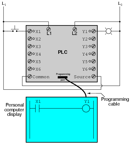
When the pushbutton switch is unactuated (unpressed), no power is sent to the X1 input of the PLC. Following the program, which shows a normally-open X1 contact in series with a Y1 coil, no "power" will be sent to the Y1 coil. Thus, the PLC's Y1 output remains de-energized, and the indicator lamp connected to it remains dark.
If the pushbutton switch is pressed, however, power will be sent to the PLC's X1 input. Any and all X1 contacts appearing in the program will assume the actuated (non-normal) state, as though they were relay contacts actuated by the energizing of a relay coil named "X1". In this case, energizing the X1 input will cause the normally-open X1 contact will "close," sending "power" to the Y1 coil. When the Y1 coil of the program "energizes," the real Y1 output will become energized, lighting up the lamp connected to it:
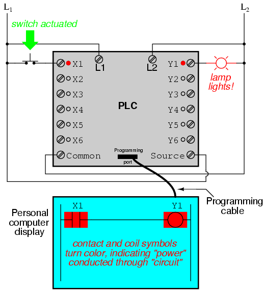
It must be understood that the X1 contact, Y1 coil, connecting wires, and "power" appearing in the personal computer's display are all virtual. They do not exist as real electrical components. They exist as commands in a computer program -- a piece of software only -- that just happens to resemble a real relay schematic diagram.

Equally important to understand is that the personal computer used to display and edit the PLC's program is not necessary for the PLC's continued operation. Once a program has been loaded to the PLC from the personal computer, the personal computer may be unplugged from the PLC, and the PLC will continue to follow the programmed commands. I include the personal computer display in these illustrations for your sake only, in aiding to understand the relationship between real-life conditions (switch closure and lamp status) and the program's status ("power" through virtual contacts and virtual coils).

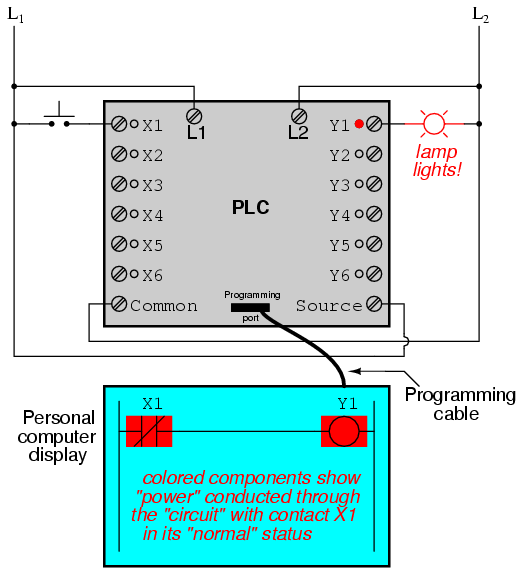
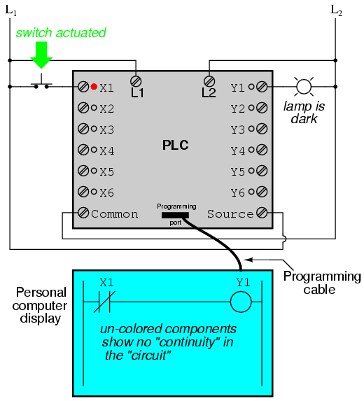
The true power and versatility of a PLC is revealed when we want to alter the behavior of a control system. Since the PLC is a programmable device, we can alter its behavior by changing the commands we give it, without having to reconfigure the electrical components connected to it. For example, suppose we wanted to make this switch-and-lamp circuit function in an inverted fashion: push the button to make the lamp turn off, and release it to make it turn on. The "hardware" solution would require that a normally-closed pushbutton switch be substituted for the normally-open switch currently in place. The "software" solution is much easier: just alter the program so that contact X1 is normally-closed rather than normally-open.

In the following illustration, we have the altered system shown in the state where the pushbutton is unactuated (not being pressed):

In this next illustration, the switch is shown actuated (pressed):
One of the advantages of implementing logical control in software rather than in hardware is that input signals can be re-used as many times in the program as is necessary. For example, take the following circuit and program, designed to energize the lamp if at least two of the three pushbutton switches are simultaneously actuated:
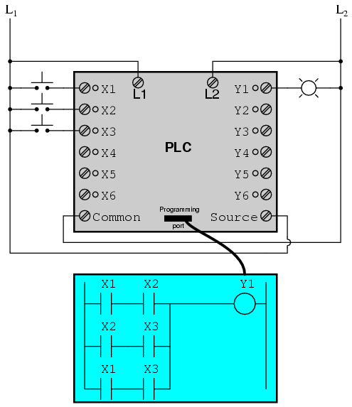
To build an equivalent circuit using electromechanical relays, three relays with two normally-open contacts each would have to be used, to provide two contacts per input switch. Using a PLC, however, we can program as many contacts as we wish for each "X" input without adding additional hardware, since each input and each output is nothing more than a single bit in the PLC's digital memory (either 0 or 1), and can be recalled as many times as necessary.
Furthermore, since each output in the PLC is nothing more than a bit in its memory as well, we can assign contacts in a PLC program "actuated" by an output (Y) status. Take for instance this next system, a motor start-stop control circuit:
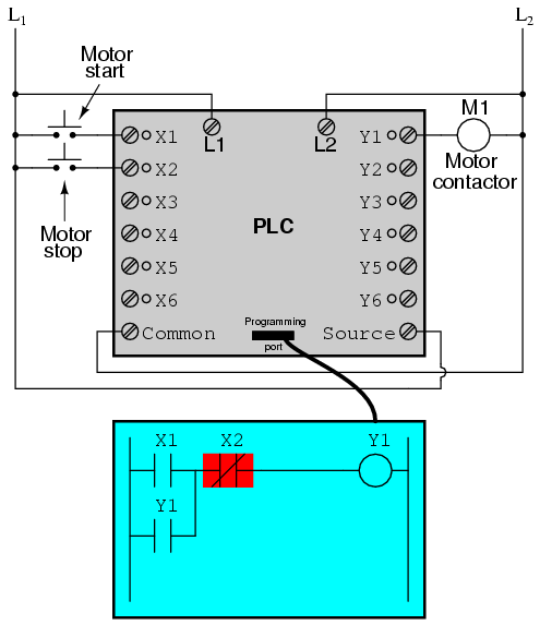
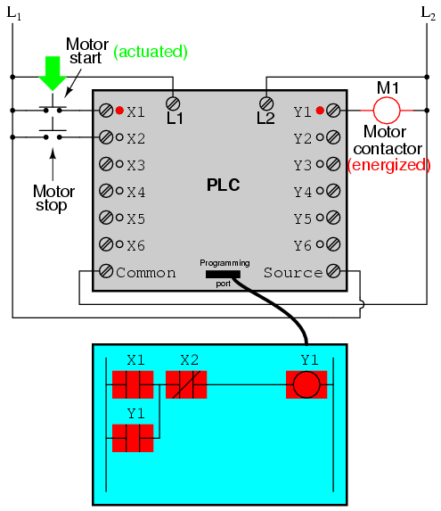
The pushbutton switch connected to input X1 serves as the "Start" switch, while the switch connected to input X2 serves as the "Stop." Another contact in the program, named Y1, uses the output coil status as a seal-in contact, directly, so that the motor contactor will continue to be energized after the "Start" pushbutton switch is released. You can see the normally-closed contact X2 appear in a colored block, showing that it is in a closed ("electrically conducting") state.

If we were to press the "Start" button, input X1 would energize, thus "closing" the X1 contact in the program, sending "power" to the Y1 "coil," energizing the Y1 output and applying 120 volt AC power to the real motor contactor coil. The parallel Y1 contact will also "close," thus latching the "circuit" in an energized state:
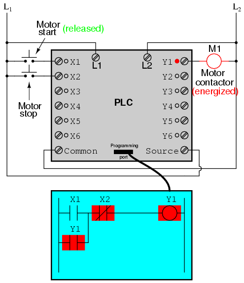
Now, if we release the "Start" pushbutton, the normally-open X1 "contact" will return to its "open" state, but the motor will continue to run because the Y1 seal-in "contact" continues to provide "continuity" to "power" coil Y1, thus keeping the Y1 output energized:
To stop the motor, we must momentarily press the "Stop" pushbutton, which will energize the X2 input and "open" the normally-closed "contact," breaking continuity to the Y1 "coil:"

When the "Stop" pushbutton is released, input X2 will de-energize, returning "contact" X2 to its normal, "closed" state. The motor, however, will not start again until the "Start" pushbutton is actuated, because the "seal-in" of Y1 has been lost:
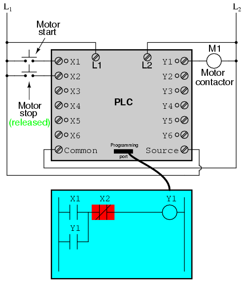
An important point to make here is that fail-safe design is just as important in PLC-controlled systems as it is in electromechanical relay-controlled systems. One should always consider the effects of failed (open) wiring on the device or devices being controlled. In this motor control circuit example, we have a problem: if the input wiring for X2 (the "Stop" switch) were to fail open, there would be no way to stop the motor!

The solution to this problem is a reversal of logic between the X2 "contact" inside the PLC program and the actual "Stop" pushbutton switch:
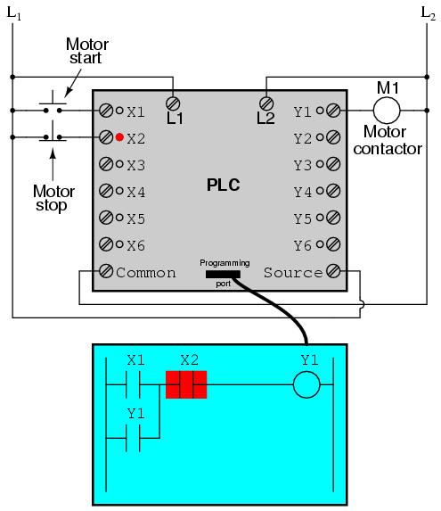

When the normally-closed "Stop" pushbutton switch is unactuated (not pressed), the PLC's X2 input will be energized, thus "closing" the X2 "contact" inside the program. This allows the motor to be started when input X1is energized, and allows it to continue to run when the "Start" pushbutton is no longer pressed. When the "Stop" pushbutton is actuated, input X2 will de-energize, thus "opening" the X2 "contact" inside the PLC program and shutting off the motor. So, we see there is no operational difference between this new design and the previous design.

However, if the input wiring on input X2 were to fail open, X2 input would de-energize in the same manner as when the "Stop" pushbutton is pressed. The result, then, for a wiring failure on the X2 input is that the motor will immediately shut off. This is a safer design than the one previously shown, where a "Stop" switch wiring failure would have resulted in an inability to turn off the motor.
In addition to input (X) and output (Y) program elements, PLCs provide "internal" coils and contacts with no intrinsic connection to the outside world. These are used much the same as "control relays" (CR1, CR2, etc.) are used in standard relay circuits: to provide logic signal inversion when necessary.
To demonstrate how one of these "internal" relays might be used, consider the following example circuit and program, designed to emulate the function of a three-input NAND gate. Since PLC program elements are typically designed by single letters, I will call the internal control relay "C1" rather than "CR1" as would be customary in a relay control circuit:
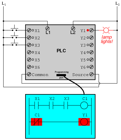
In this circuit, the lamp will remain lit so long as any of the pushbuttons remain unactuated (unpressed). To make the lamp turn off, we will have to actuate (press) all three switches, like this:
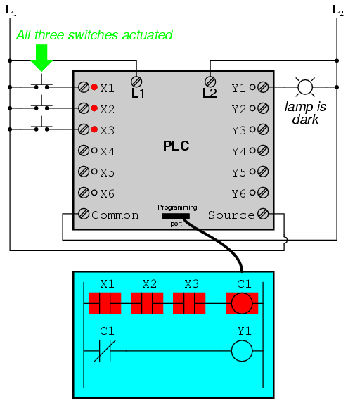
This section on programmable logic controllers illustrates just a small sample of their capabilities. As computers, PLCs can perform timing functions (for the equivalent of time-delay relays), drum sequencing, and other advanced functions with far greater accuracy and reliability than what is possible using electromechanical logic devices. Most PLCs have the capacity for far more than six inputs and six outputs. The following photograph shows several input and output modules of a single Allen-Bradley PLC.
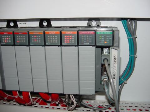
With each module having sixteen "points" of either input or output, this PLC has the ability to monitor and control dozens of devices. Fit into a control cabinet, a PLC takes up little room, especially considering the equivalent space that would be needed by electromechanical relays to perform the same functions:

One advantage of PLCs that simply cannot be duplicated by electromechanical relays is remote monitoring and control via digital computer networks. Because a PLC is nothing more than a special-purpose digital computer, it has the ability to communicate with other computers rather easily. The following photograph shows a personal computer displaying a graphic image of a real liquid-level process (a pumping, or "lift," station for a municipal wastewater treatment system) controlled by a PLC. The actual pumping station is located miles away from the personal computer display:


Source:http://www.allaboutcircuits.com/vol_4/chpt_6/6.html

To Know more about PLC Training and Industrial Automation Engineering Course For BTech/BE Students.

Monday 13 October 2014

Learn Allen Bradley PLC Programming | Sofcontraining.com

 FLEX LOGIX CONTROLLER SYSTEM COMPONENTS IDENTIFICATION


I: FlexLogix Platform

For distributed-control:
• (i.e., control platform is located at or close to the process/machine).
• Allows application to be simplified by dividing it.


This system has the following characteristics:
• Reduced size for smaller spaces
• Can be mounted on a DIN rail or panels
• Can be mounted vertically or horizontally
• Modular


FlexLogix Hardware


II. Flex Logix Main Component


FlexLogix Main Component

Flex Logix Features:
• 64 Kbyte (1794-L33) and 512 Kbyte (1794-L34) fixed memory:
• 1794-L33/A and 1794-L34/B support non-volatile memory to retain project without a battery
• Two communications slots installed in controller
• Support for NetLinx™ networks:
  – EtherNet/IP
  – DeviceNet
  – ControlNet


FlexLogix I/O placed on DIN rail:
• Supports one or two banks
  – (up to 8 local I/O modules and 8 extended local I/O modules)
Flex IOs

FlexLogix I/O placed on DIN rail:
• Extended local I/O modules can be located 1 to 3 m from local I/O
• FlexLogix systems support up to 512 I/O points

NOTE: FLEXLOGIX BANKS CAN EXTEND UP TO 10 FT. (3 METERS) WHEN USING EXTENDER CABLE.

III. FLEX LOGIX COMMUNICATION.
Connected directly to the controller in the daughtercard slots:


Easy Learn Allen Bradley PLC Programming

RSLOGIX 5000 SOFTWARE COMPONENTS


I: RSLogix 5000 Programming Software.

Tip: Because all Logix5000 platforms have

All ControLogix, FlexLogix, and CompactLogix PLC types used common control engine, RSLogix 5000 software is used to program and configure all Logix5000 systems.

Used to perform the following tasks:
• Develop and modify code
  – (e.g., ladder logic, function block diagrams, Structured Text etc.)
• Monitor project and system component operation during operation
• Configure hardware modules (communication module, I/O module, etc..)


II. RSLogix 5000 Software Advantage.

RSLogix 5000 software offers the following benefits:
• Flexible, easy-to-use, Windows®-based editors and components
• I/O configuration wizards
• Ability to copy and paste components between projects
• Same look and feel as RSLogix 5 and RSLogix 500 software:
   – Ladder logic instruction set built on PLC® instruction set
• Multiple programming language options
   – ladder logic, function block diagram, sequential function chart, and structured text.
• Your configuration will depend on the language options selected and installed.


III. RSLogix 5000 Software Windows.

Main Screen at Default Configuration
1. Toolbars
2. Controller Organizer
3. Routine Editor / Tags Window
4. Results Window


IV. RSLogix 5000 Toolbars.

Following toolbars are available:
• Standard toolbar
• Online toolbar
• Path toolbar
• Language Element toolbar


Standard Toolbar: Standard Microsoft options:
• New
• Save
• Cut
• Copy
• Paste
• And more


Standard Toolbar

Online Toolbar: toolbar that provides controller status. Tab/drop-down lists are available for viewing related information:


Online Toolbar


Path Toolbar: toolbar specifically used for communicating with controller and viewing communication status:


Path Toolbar Screen


Language Element Toolbar: toolbar containing programming elements, grouped by tabs, for entry into an active routine. Each language has its own element toolbar:


Language Element Toolbar

V. Controller Organizer


Controller Organizer
 
Above is showing the Expanded Branch/TASK,  Main Routine, and Sub-Routine in hierarchy.

NOTE: THE CONTROLLER ORGANISER CAN BE OPENED OR CLOSED BY USING THE TOGGLE ORGANISER WINDOW BUTTON.

Routine Editor/Tags Window: Displays open routine or tags collection opened through Controller Organizer:

Routine Editor Tags Window


Results Window: window at bottom of main window that contains the following tabs:

Results Tabs
• Errors tab: Results of verification for errors in the project
• Search Results tab: Results of a search for a project component
• Watch tab: Window for viewing data in an open routine


Sunday 12 October 2014

Using a Framework for a PLC Project | Sofcontraining.com

Why should I use a framework for my control and automation projects?

Before we start looking at the reasons for using a common framework, I’ll start by explaining what it is I mean by it.
Simply, a framework is a piece of software or a library that provides generic or common predefined functionality. The framework is reusable and can be extended by a user in order to provide a bespoke / custom solution.

Advantages
Efficiency and Cost
The framework will typically provide up to around 50% of the application developments features thus resulting in a huge saving in time. In addition, the use of predefined, pre-tested code will dramatically reduce development and coding time.
Improved documentation and customer support.
Once again, the use of the software framework and predefined code will speed up the production of manuals as much of the content relating to common automation tasks can be written once and used time and time again.

Quality
The use of predefined , pre-tested code dramatically improves the quality of the software product, ensuring consistency and fewer programming errors.

I’m going suggest two frameworks.
The first shall cover PLC and the second HMI.

PLC Framework
The framework should be split into program areas covering,
  • Version
  • Constants
  • Global Code and Startup
  • Input Mapping
  • Safety Interface
  • Interlocks
  • Recipe Handling, Engineering SP
  • Data mapped from the HMI or SCADA
  • Data mapped to the HMI or SCADA
  • Device Handlers
  • Alarm Handling
  • Output Mapping
  • Communications setup
  • Statistics
  • Any program sequences.
The picture below demonstrates this. The example shown was created using Mitsubishi GXWorks 2.
Note: The program naming does not dictate program flow as this can be set elsewhere.
 framework
HMI Framework
The HMI framework should incorporate the following generic features:
  • Security – Predefined levels of access
  • Multi Language Support
  • Alarm Handling
  • Logging
  • Trending
  • Common Icons, Pushbuttons and displays

Friday 10 October 2014

Schneider Electric with PLC Scada Automation | Sofcon.com

A post-Invensys-acquisition update
By Rick Zabel, Publisher & Editor

  Last week in Orlando, FL, Schneider Electric hosted its first Global Software Customer Conference since it acquired Invensys in January. The conference has its roots as WonderWorld, the former Wonderware company’s own user conference. Over the years, after Invensys acquired Wonderware, the conference evolved into OpsManage, a global event that emphasized all of Invensys’ software, control, and safety offerings. Since Schneider Electric's purchase of Invensys, I have been waiting to hear some news about the integration of the two companies. That news, as it relates to software, was delivered last week at the conference.

In April of this year, Schneider Electric created a new business unit called Global Solutions. Global Solutions is made up of four key offerings. One of those offerings is Software, which will continue to be led by Ravi Gopinath as Executive Vice President. The Software business consists of the legacy Invensys brands—Wonderware, SimSci, and Avantis—as well as Schneider Electric’s Citect, Ampla, and OASyS DNA (Telvent SCADA) software brands, integrated into one business.
In addition to the Software business, Global Solutions consists of the following offerings:
  • Field services and product support applicable to other Schneider Electric product offerings.
  • Segments, activities related to industry-specific and key account level, global sales and after-market customer relationship management.
  • Digital services, which is a basket of offerings that may or may not leverage software. Examples include cyber security risk assessment services and Telvent weather forecasting service.
Global Solutions and its President, Daniel Doimo, will be headquartered in Lake Forest, CA, which has long been the headquarters for Wonderware and the Invensys software business. Doimo stressed that software is a key pillar to Schneider Electric's global strategy. "We invested in software because we have the vision," said Doimo. "We don't want to reinvent the wheel - we want to spin it faster." Schneider Electric’s Global Solutions business will deliver holistic and integrated solutions to its customers. They are committed to tailored solutions for specific industry segments. Doimo and Gopinath believe the more robust, combined solution set offers the most comprehensive portfolio to help its customers achieve operational efficiency. However, Gopinath stressed, "We are always looking for opportunities to strengthen our portfolio through acquisitions."

Improving the user experience and driving additional value are the cornerstones of everything the company does. Gopinath said the software business has and will continue to focus incessantly on improving user experience, even as the customer persona is rapidly changing. Their second focus is interoperability, which is where architecture comes into play.

Software Architecture

At the core of its software solutions, and at the lowest layer of the architecture, is a common platform called Wonderware System Platform. It is the information management framework for all of the company’s software products. It is open, scalable, and secure, and it works across multiple hardware platforms. The second layer consists of applications that perform specific functions, like HMI, historian, MES, asset management, etc.  The third layer encompasses solutions for specific industry segments.


Prior to the Invensys acquisition, Schneider Electric introduced StruxureWare, a unique software platform of integrated applications and suites that delivers visibility into energy and resource use across an organization. The StruxureWare concept and name will be used in the newly combined software business. StruxureWare will be a collection of applications or solutions that are tailored to specific industry use cases.  They will provide specific, unique functions required by industry segments. A few of these StruxureWare offerings have been defined, but they are still early in the process of defining others.

Thursday 9 October 2014

Understanding The Programming Of The PLC

The programming of the plc is a procedure of making commands, arrangements, and measurements used by the PLC to make control on a machine or operation. The body of this process is the plc and the program is the brain.In fact, the programmed PLC makes a machine looks like a human. PLC stands for programmable logic controller.A PLC has begun in the 1960's by Modicon Company. 

Its initial application was in the cars production factories in which it removed the old relays and replaced it with the plc.

As usual, a better solution is always in a creative mind, though it was a simple decision and control system effective for the era. Quickly, a communication can be a mechanized switch operated by an electric supply to switch it on and off. 

Getting mechanized by nature is big compared to electronic devices and transferring components usually degrade and wear, and finally are unsuccessful. Producing the preferred relay common sense needs many relays and many more wires in order to connect them. Rewiring is needed if the logic is wrong or needs to be updated.
The PLC reduces many of these actual relays to create common sense which moves and circuits them almost to the software. PLC development has typically been and still at Step ladder Diagram or Step ladder Common sense. It continues to be mostly employed language for encoding a PLC, despite the fact that you will find choice spoken languages. The basic reason is, it is rather like the electric powered schematics employed for communicate reason.

Ladder reasoning is programmed using frequent power icons like those utilized for contacts and coils. A step ladder diagram program appears to be a power drawing that electricians are comfortable and familiar with, very easy adoption from the difficult-wired relays for the PLC was attained. Programming a PLC demands a certain knowledge and skill.

Comprehending the method that will be operated or programmed is paramount. Start-up and Shutdown characteristics tend to be overlooked or provided little focus at the start in which the concentration is in the principal features of the machine or process. The PLC should be picked to match the application as well as each one of the outputs and inputs accounted for and extras integrated in the event that the task expands or to deal with components that have been basically overlooked. Planning upfront will save time and frustrations later, as with all projects.


Getting together with all the stakeholders or those engaged might be a wonderful initial step. Hash out the range and establish a time-range and possess individuals included agreement to it. Later on, when extra features or characteristics are asked for, you can support the explanation of the coding task getting more than initially proposed.

PLC coding is only area of the whole job of automating a piece of equipment. An expert must layout and stipulates the ingredients that provide the PLC with its inputs and outputs that are going to control. If you are only responsible to programming the plc, so you need all the inputs and outputs lists and their specs from the engineer.

He or she will also be the main one to deliver a controlled narration or information from the project. Undertaken one step more in advancement, Boolean Reason diagrams might be provided to you the developer which can (if in depth adequate) be used to create the program. Quite often the Handles Electric Engineer will also carry out the programming and perhaps the HMI coding... but which is another subject.


So in wrapping it up, PLC programming is about giving brains to machines processes using a specialized computer and requires significant knowledge and skills. I will tell you it can be a very fulfilling job when it comes to struggle, constant studying, teamwork and last and positively not very least, monetarily get.